Instruction This workshop manual describes the main maintenance items and procedures and troubleshooting for the Husqvarna Zenoah engine blower. This manual is classified into two categories; one includes important notices concerning disassembly and reassembly including "Cautions for disassembly" and "Cautions for reassembly", the other includes inspection and adjustment items such as "Muffler inspection and maintenance", "Air cleaner inspection" and "Carburetor adjustment".
Exported models according to country This workshop manual applies to all exported engine blower models sold by Hasqvarna Zenoah. Some models are not exported to particular regions of the world. Please check your model by referring the following table. Table of exported models corresponding to country Category Handheld Blower Displacement 22.5 cm Engine Type G23L JAP Blower Model 3 25.4 cm Backpack Blower 3 GZ25N GZ30N 41.
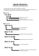
Model Notation The engine type and blower model nomenclature is as follows. The applicable blower models and series names are indicated at right of the maintenance item title. Refer to this nomenclature to confirm engine type and blower model.
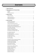
Contents 1. Special Features ............................................................................................................ 1 2. Specifications and Technical Data 2-1 Blower ........................................................................................................................... 2 2-2 Pipe ............................................................................................................................... 3 2-3 Overall dimensions ....................................
5. Structure of Right Hand Throttle Lever ............................................................. 40 6. Carburetor 6-1 Specifications .............................................................................................................. 41 6-2 Carburetor Configuration ............................................................................................ 42 6-3 Carburetor Conforms to Exhaust Emissions Regulations ..........................................
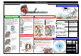
1. Special Features Pipe End Specifications and Characteristics Operating area Pipe End φ57 mm (2.24 in.) Pipe End φ72 mm (2.84 in.)/ φ66 mm (2.60in.) Engine The environmental friendly Strato Charge Engine is installed. Centrifugal Fan Open Vane Fan The exhaust gas toxin concentration is greatly reduced without need for a catalyst, to generate reactive heat. High engine cooling performance promotes stable output even during continuous operation in summer.
2. Specifications and Technical Data 2-1 Blower Item Category Engine Type ★:Left hand throttle lever specifications ★: Unit Specifications Handheld Blower G23L HB23 Series Blower Model Sales Region (Reference) G4K - GZ48N - EBZ3000RH/ EBZ3050RH EB4300 EBZ4800 EBZ5100/ EBZ5100RH/ EBZ5150/ EBZ5150RH EBZ5100Q/ EBZ5150Q EB6200 EB7000 EB7001 EBZ7100/ EBZ7100RH/ EBZ7150/ EBZ7150RH/ JAP, General JAP, EU, General USA USA General EU, General JAP USA ← ← ← 40 (1.575) 33 (1.299) 41.
2. Specifications and Technical Data 2-2 Pipe Unit: mm (in.) Part Name Grip Assembly Vacuum Kit Pipe End φ66 (2.60) Form Straight Pipe+ +Duckbill Nozzle φ57 (2.24) φ72 (2.84) Diameter: D φ66 (2.60) 138 (5.43) 180 (7.19) 30 (1.18) 23 (0.91) Standard RedMax Lodo Solid Color EB430/ EBE440 HB2302/ HB2311EZ/ HBZ2601 EBZ3000 EB4300/ EB6200/ Model EB7000 EBZ4800 EBZ5100Q EBZ5100/ EB7001 EBZ7100 EBZ8001 Part Number D=φ60 (2.36) D=φ74 (2.91) D=φ80 (3.
2. Specifications and Technical Data 2-3 Overall dimensions Handheld Blower Blower Type HB2302 HB2311EZ HBZ2601 HBZ2601 (USA) A 325 (12.8) 325 (12.8) 327 (12.9) B 225 (8.86) 233 (9.17) 268 (10.55) 269 (10.59) C 360 (14.2) 360 (14.2) 360 (14.2) Unit: mm (in.) D 610 (24.0) 610 (24.0) 610 (24.0) Backpack Blower Blower Type A 313 EBZ3000/ 3000RH/ 3050/ 3050RH (12.3) 335 EB4300 (13.2) 352 EBZ4800 (13.9) 401 EBZ5100/ 5100RH/ 5150/ 5150RH (15.8) 401 EBZ5100Q/ 5150Q (15.8) 336 EB6200 (13.2) 336 EB7000 (13.
3.
3. SPECIAL TOOLS Handheld Blower: HB23 Series, HBZ26 Series 【HB23 Series】 】 【HBZ26 Series】 】 Stopper 2. Set the stopper (special tool) into the plug hole. Stopper Fan 3. Remove the mounting nut using the box wrench then remove the fan. Washer 4. Remove the extension using the wrench. Washer Mounting Nut (12 mm Hex) Wrench (17 mm) Box Wrench (12 mm) Extension 5. Remove the four mounting screws, separate the volute case and the engine short block.
3. Special Tools Handheld Blower: HB23 Series, HBZ26 Series Puller Bolt (8 mm) 17 mm Puller Assy 6. Remove the rotor using the puller assy. Apply 8 mm puller bolts. Rotor How to use (Procedure) Backpack Blower: EBZ30 Series Construction Refer to “4-3 Upper Spring Damper Removal” Clip (4) Air Inlet Net Refer to “4-2 Air Inlet Net Removal” Mounting Screw (8) TORX (T27): M5×L25 Mounting Screw (3) Mounting Screw (2) TORX (T27/ P): M5×L70 Plate Volute Cover Assy.
3. SPECIAL TOOLS Backpack Blower: EBZ30 Series 2. Set the stopper (special tool) into the plug hole. Stopper 3. Remove the four mounting screws, then remove the fan. Fan Mounting Bolt TORX (T27): M6×L30 Mounting Bolt TORX (T27): M5×L20 4. Remove the four mounting screws, separate the volute case and the engine short block.
3. Special Tools Backpack Blower: EBZ30 Series 5. Remove the mounting nut using the box wrench. Box Wrench (12 mm) 6. Remove the rotor using the puller assy. Apply 8 mm puller bolts. Mounting Nut (12 mm Hex) Puller Assy.
3. SPECIAL TOOLS Backpack Blower: EB4300/ 6200, EB70 Series, EBZ4800, EBZ51/ 71/ 80 Series 2. Set the stopper (special tool) into the plug hole. Stopper 3. Remove the four mount screws, then remove the fan. The fan is detached but stays inside the volute cover assembly and the volute case. Mounting Bolt Fan Volute Case Volute Cover Assy. Engine Short Block 4. Remove the six mounting screws then remove the engine short block from the volute case. Mounting Bolt Volute Case 5.
3. Special Tools 3-2 Module Assembly Description Part Name Part Number Gauge 3350-96240 T=0.4 mm Gauge 2750-96240 t=0.3 mm Gauge 848-8W4-0050 t=0.4 mm Wrench (HEX) 3304-97611 Size: 3/ 4/ 5 mm Wrench (TORX) 2850-96410 Size: T20/ T25/ T27 Model HB23 Series HBZ26 Series EBZ30 Series ● ● EB4300/ 6200 EB70 Series EBZ4800/ 5100Q ● ● EBZ5100 EBZ71/ 80 Series ● ● Adjust the air gap between the rotor's magnetic steel and the module using the gauge (special tool).
3. SPECIAL TOOLS Examples of the gauge (special tool) usages are shown according to the type of the gauge. Gauge: 3350-96240 (T=0.4 mm) HB23 Series, HBZ26 Series, EBZ30 Series 【HB23 Series】 】 Wrench Rotor 1. Remove the obstructive parts in order to see the rotor and the module. (Refer to “3-1 Rotor Removal”.) 2. Insert a gauge (special tool) between the rotor magnet metal and module. Tighten the mounting bolts while pushing the module against the rotor.
3. Special Tools Gauge: 2750-96240 (T=0.3 mm) EB4300/ 6200, EB70 Series, EBZ4800/ 5100Q 1. Remove the module cover. 【EB4300/ 6200, EB70 Series】 】 Gauge 2. Insert a gauge (special tool) between the rotor magnet metal and module. Tighten the mounting bolts while pushing the module against the rotor. Wrench Rotor Mounting Bolt 【EBZ4800/ 5100Q】 】 Module Wrench Gauge Rotor Module Mounting Bolt Gauge: 848-8W4-0050 (T=0.4 mm) EBZ5100, EBZ71/ 80 Series 1. Remove the module cover. 【EBZ5100】 】 Rotor 2.
3. SPECIAL TOOLS 3-3 Recoil Pulley Removal Description Part Name Part Number Stopper 4810-96220 Puller 4500-96100 Puller 848-8W0-0020 Wrench (HEX) 3304-97611 Size: 3/ 4/ 5 mm Wrench (TORX) 2850-96410 Size: T20/ T25/ T27 Model HBZ26 Series ● EBZ71/ 80 Series ● ● ● ● ● Remove the recoil pulley using the puller (special tool) while preventing piston movement by setting the stopper (special tool). Examples of the puller (special tool) usages are shown according to the type of the puller.
3. Special Tools 3-4 Piston Pin Removal Description Part Name Part Number Rod Assy 1101-96220 φ7.5×φ4.7 Rod Assy 3350-96230 φ11×φ8 Rod Assy 2750-96230 φ11×35 mm Wrench (HEX) 3304-97611 Size: 3/ 4/ 5 mm Wrench (TORX) 2850-96410 Size: T20/ T25/ T27 Model HB23 Series HBZ26 Series ● ● EBZ30 Series EB4300 ● EB6200 EB70 Series ● ● EBZ4800 EBZ51 Series ● EBZ71/ 80 Series ● ● ●(Only a rod is used.) ● Remove the cylinder, and then the piston pin using the rod assy (special tool).
3. SPECIAL TOOLS Rod Assy: 3350-96230 EBZ30 Series, EB4300, EBZ4800, EBZ51 Series 1. Remove the engine short block (refer to “3-1 Rotor Removal”) and then remove the cylinder. Piston Rod assy. Piston Pin 2. Remove the snap rings from both sides of the piston pin. 3. Insertion the rod assy (special tool) against the piston pin and gently tap with a plastic hammer to push out the pin. CAUTION Hard hammering may damage the big end of the connecting rod.
4. Service Guide 4-1 Starter Pulley Removal HB23 Series, EBZ30 Series ● Insert the stopper (special tool) into the plug hole (refer to “3 Special Tool”) to secure the piston. Pliers ● Remove the starter pulley using commercially available pliers. The pulley must be covered with cloth to prevent from damage. CAUTION Never remove the starter pulley by hitting with a hammer. Doing so may damage the pulley.
4. Service Guide 4-3 Upper Spring Damper Removal EBZ30 Series To remove the upper spring damper, follow the procedure below. 1. Remove the three mounting screws. Plate 2. Pull the plate upward from the spring holder’s groove. Mounting Screw TORX (T27): M5×L25 Spring Holder 3. Press the upper part of the volute to the frame to slacken the strap, and then pull out the plate. Strap Plate 4. Pull the strap out from the volute case. Screwdriver 5.
4. Service Guide 4-4 Volute Cover Lower Damper Removal EB6200, EB70 Series, EBZ4800, EBZ30/ 51/ 71 Series Volute Cover Mounting Screw ● Remove the volute unit from the frame. ● Remove the all mount mounting screws, separate volute cover from its case, then remove the lower damper unit. Volute Case Lower Damper EBZ80 Series Cover Mounting Screw ● Remove the volute unit from the frame. ● Remove the cover by removing the three mounting screws then remove the lower damper from the volute case’s groove.
4. Service Guide 4-6 Crankcase Oil Seal and Bearings Removal All Models 【Fan Side】 】 Press Bearing Guide ● Disassembly is usually unnecessary. However, if the oil seal’s main lip or dust lip is worn, the shaft will become loose due to bearing wear or if the they have seized, replace the oil seal and bearings with new ones. ● Be sure to use the press to remove the bearings. CAUTION Be sure to use the press to press the bearings out during bearing removal. Without jig use to the crankcase may be damaged.
4. Service Guide 4-7 Crankcase Assembling Bearings, snap ring, oil seal configuration and installation position differ depending on type. Properly install each part and reassemble the crankcase referring to the corresponding type’s drawing. For bearing and oil seal installation, refer to the explanation on page 23. HB23 Series, HBZ26 Series Construction Snap Ring Bearing Push the bearings until they contact the crankcase.
4. Service Guide EBZ4800, EBZ51 Series Construction Lubrication Hole Lubrication Hole Bearing Push the bearings until they contact the crankcase. Snap Ring Do not cover the lubrication hole with the snap ring. 【Starter Side】 】 【Fan Side】 】 Oil Seal Oil Seal Push the oil seal within 1.5 to 2.3 mm (0.06 to 0.09 in.) from the crankcase surface. Bearing Push the bearings until they contact the snap ring. Push the oil seal within 0 to 0.5 mm (0.02 in.) from the crankcase surface.
4. Service Guide Oil Seal Assembly All Models ● Never insert the oil seal obliquely. The oil seal may be fall out. Press ● Before the oil seal is pressure-inserted, apply grease to the oil seal. 【Crankcase Outside】 】 ● Press the oil seal from the outside of the crankcase using combined special tools (holder and guide). ● Pay attention because oil seal pressure-insertion position differs according to rotor, starter and engine type.
4. Service Guide 4-8 Piston Inserting Direction All Models Triangle Mark Arrow Mark Make sure to point the recessed mark (arrow or triangle) on the piston head to the exhaust (muffler) side. 【Exhaust Side】 】 【Exhaust Side】 】 4-9 Piston Pin Snap Ring Assembly End Gap Position HB23 Series, HBZ26 Series, EB4300/ 6200, EB70 Series Fit the snap ring in the piston’s groove firmly and position the end gap of the snap ring below the piston.
4. Service Guide 4-10 Positioning of Lead Air Intake Tube HBZ26 Series The lead air intake tube has cast marking of either “F” or “S”. “S” is for the starter end, and “F” for the fan end. Assembling position shall not be mixed up. Marks CAUTION Caution: Oppositely assembled tubes will cause a sealing failure. Before assembling the tubes, check for deterioration or cracks and change will new ones if necessary. Lead Air Intake Tube 4-11 Reed Valve Assembly HBZ26 Series Valve Case Valve Case Max. 0.
4. Service Guide 4-12 Gasket Assembly All Models Gasket Positions C, Muffler Gasket 【Fan Side】 】 Each gasket has its installing direction. Pay attention to the direction when the gasket is being installed. CAUTION When the engine is overhauled, replace the gaskets with new ones.
4. Service Guide 4-13 Scavenging Duct Cover Assembly EBZ30/ 71/ 80 Series Gasket The scavenging duct covers have marking either “S” for starter side or and “F” for fan side. They must not be oppositely assembled. CAUTION When the engine is overhauled, be sure to replace the gaskets with new ones. Gasket “F” Scavenging Duct Cover “S” Scavenging Duct Cover REFERENCE EBZ4800, EBZ51 Series Strato Charged engines have no scavenging duct covers.
4. Service Guide 4-15 Switch Cord Assembly Switch Cord Assembly HB23 Series, HBZ26 Series ● Fit the switch cord connector firmly to the module’s terminal. 【HB23 Series】 】 Switch Cord Module Connector 【HBZ26 Series】 】 Switch Cord ● Secure the switch cord terminal with the module mounting bolt. Module Connector Terminal Switch Cord Assembly About 45 Degrees EBZ30 Series Switch Cord Terminal Connector ● Secure the switch cord terminal (black) with the module mount bolt.
4. Service Guide Switch Cord Assembly EB4300/ 6200, EB70 Series ● Secure the switch cord terminal with the module mounting bolt. Module CAUTION Ensure the cord is not bent nor interfering with the crankcase when the module mount bolt is tightened. ● Bends the terminal of the module, fit the switch cord connector firmly to the module’s terminal. CAUTION Bend the module’s terminal until the cord is clear of the crankcase.
4. Service Guide 4-16 Cable Wiring Switch Cord Wiring HB23 Series, HBZ26 Series ● Insert the grommet to align with the volute case notch and clamp the cord between the protrusions as shown in the figure at left. Cords Grommet CAUTION Check that the cord on the module side is not caught between volute case and crankcase. ● Pay attention that the cord is not caught against the engine cover when it is installed.
4. Service Guide 4-17 Fan Assembly All Models ● Insert the stopper (special tool) into the plug hole (refer to “3 Special Tool”). 【HB23/ 26 Series】 】 Fan Mounting Bolt Torque: 7.8~11.8N・m (80~120kgf・cm) ● Tighten the mounting nut so that the fan securely meets the rotor without looseness. CAUTION Mounting Nut Torque: 9.8~14.7N・m (100~150kgf・cm) If the fan is installed with four mounting bolts, secure them with equal pressure in diagonal order.
4. Service Guide 4-20 Upper Damper Assembly EB4300/6200, EB70 Series, EBZ4800, EBZ51/ 71/ 80 Series Assemble the damper and volute cover by mating their protrusions. CAUTION Check that the damper is not tilted. Improper installation will result in rapid damage.
4. Service Guide 4-22 Carburetor Assembly EBZ71/ 80 Series Tighten the screws of the earth cord between the carburetor's adjuster unit and the crankcase. Carburetor CAUTION This cord prevents electrostatic sparks. Do not fail to connect it. Earth Cord 4-23 Engine Cover Assembly Check of the Gasket Assembly Engine Cover HB23 Series When the engine cover is installed, pay attention to installing the muffler’s gasket to the inside the cover to protect the fuel tank from heat.
4. Service Guide 4-24 Check of the Gasket Assembly EBZ4800, EBZ51/ 71/ 80 Series 【Intake Side】 】 Insulator Gasket Cylinder Plate 【Exhaust Side】 】 Muffler Gasket Cylinder Plate Check that the master and insulator gaskets are set inside the cylinder plate before the engine cover is installed. CAUTION If the gasket is improperly set, engine cooling performance will be reduced.
4. Service Guide Husqvarna Zenoah engine blowers are equipped with spark arresters to prevent spark dispersion. CAUTION ・ The Spark arrester prevents burnt carbon discharging from the muffler. Even though the spark arrester can easily clog with carbon, never operate the blower with the spark arrester detached. ・ The EB4300 and EBZ4800 (Japanese specifications) are not equipped with spark arresters. 4-25 Spark Arrester Removal HB23 Series, HBZ26 Series 1. Remove the engine cover. (Refer to “3.
4. Service Guide EBZ51/ 71/ 80 Series Muffler 1. Remove the engine cover. (Refer to “3. Special Tools”) Mounting Bolt (long) ×2 2. Remove the three mounting bolts and then remove the muffler. Torque: 7.8~11.8N・m (80~120kgf・cm) Mounting Bolt ×4 3. Remove the four mounting bolts (torx) and then attach the diffuser (diffusing cover) and the spark arrester.
4. Service Guide 4-28 Air Cleaner Inspection This device blows fallen leaves to a collection point but at the same time small particles (dust and sand) become airborne. If such dust invades the engine, the engine mechanism will wear quickly. So periodically check and clean the element according to the following table. CAUTION ・ The power blower operating environment is very dusty so the air cleaner will clog more quickly than that of other power tools.
4. Service Guide Single layer half-wet urethane foam EB4300/ 6200 Loosen the knob then remove the element. Screen Knob Cover Knob Element Screw Dual layer half-wet urethane foam EBZ4800 Loosen the knobs then remove the elements. Elements Yellow Black Screen Knobs Packing Knobs Cover Single layer half-wet urethane foam EBZ51 Series Loosen the knobs then remove the element.
4. Service Guide Two stage dry element (Pre-filter + Paper filter) EBZ80 Series Loosen the knob bolts then remove the element (pre-filter + paper filter). Knob Bolts Pre-filter Cover Case Paper Filter 4-30 Element Cleaning Element and pre-filter rinsing All Models ● Rinse the element carefully with warm water diluted detergent or washing oil. CAUTION Confirm that no deformity, damage or deterioration (if touched, element will crumble) exists. If necessary replace it with a new one.
5. Structure of Right Hand Throttle Lever ● The right hand throttle lever specifications (RH) employs a governor mechanism for easy blower operation with constant wind pressure. It is a mechanism where the throttle lever can be fixed by a throttle lever lock at a chosen position. The suitable engine speed can be set for operating load.
6. Carburetor 6-1 Specifications Model Carburetor (Walbro) Carburetor Specifications Seal (L-needle) Metering Lever Valve Opening Valve Closing Pressure Height Pressure 2 2 mm (in.) kg/ cm (kpa) kg/ cm (kpa) Sales Region Blower Model Engine Type Type Name Part Number Part Name Part Number Adjustment angle (L-needle return angle) EU/ General HB2302 G23L WYJ-110A 5516-81000 Limiter Cap 848-F40-80D0 Adjustment FIXED # 38 ― 9 (0.354) 17 (0.669) 1.5±0.16 (0.059±0.006) 1.3~2.3 0.6~1.
6. Carburetor 6-2 Carburetor Configuration Inspection and adjustment items Execute the following check and adjustment if the carburetor does not function normally. (Refer to "6-5 Idling Speed Adjustment " and "6-6 Carburetor Inspection".
6. Carburetor 6-3 Carburetor Conforms to Exhaust Emissions Regulations The carburetor flow rates of all Hasqvarna Zenoah engine blowers are individually pre-adjusted to pass exhaust emissions regulations. A limiter cap is installed in the idling limiter to prevent an operator carelessly changing the idle setting resulting in non-conformance with exhaust emission regulations. Execute a correct adjustment according to "6-7 Carburetor Adjustment".
6. Carburetor 6-4 Limiter Cap Removal/ Installation Tool Limiter cap tool extraction side Limiter Cap Tool Screw unit (M2 counterclockwise threading) The limiter cap tool (carburetor maintenance tool: 848-8W9-0080) is used for limiter cap installation/removal. Limiter cap insertion side Removal Limiter cap tool extraction side Press it while turning it counterclockwise. Pull it out.
6. Carburetor High Speed Adjustment 【USA/ HBZ2601 only】 】 Increases High speed revolutions are adjusted by a H-needle. Clockwise (CW): Fuel mixture becomes lean. (Speed increases.) Counterclockwise (CCW): Fuel mixture becomes rich. (Speed decreases.) H-needle Decreases 6-6 Carburetor Inspection Inlet Valve Leaking Test Connect a leak tester to the fuel inlet port of the carburetor.
6. Carburetor b. Judgments of the main check valve ● As illustrated, hold a plastic pipe on the check valve and blow and suck air by your mouth. If the air is stopped by blowing, and open by sucking, the valve has no failure. Plastic Pipe Main Check Valve Body Assembly ● In case of failure, soak the valve into gasoline for about 10 minutes and repeat blowing and sucking several times. If this is not successful, replace the body assembly.
6. Carburetor 6-7 Carburetor Adjustment Before performing carburetor adjustment, the following areas must be inspected for good working order. ● Correct spark plug set to specified gap must be installed. ● The air filter and paper filter must be clean and properly installed. ● The muffler spark arrestor screen and exhaust port must be clear of carbon. ● The fuel filter must be clean and properly installed. ● The carburetor and carburetor insulator block screw must be tight.
6. Carburetor Adjustment if engine does not activate Set the adjustable parts as specified according to the following procedure. L-needle 1. Loosen the throttle valve adjust screw until the throttle valve becomes completely free, then turn the screw clockwise until the regulated angle is attained. (Refer to "6-1 Specifications- Adjustment Angle for Engine Start".) Throttle Valve Adjust Screw 【USA/ HBZ2601 only】 】 H-needle 2. Turn the idling limiter (L-needle) counterclockwise until it becomes free.
6. Carburetor Rich Down Adjustment 1. Turn the idling limiter (L-needle) clockwise to the position of maximum engine speed. L-needle 2. Turn the throttle valve adjust screw in either direction to match to the regulated ID peak speed. (Refer to "6-1 Specifications- ID Peak Engine Speed".) Throttle Valve Adjust Screw 3. Turn the L-needle counterclockwise and execute the rich down adjustment. (Refer to "6-1 Specifications- ID Rich Down".
6. Carburetor Confirmation after adjustment Dust Cover ● After adjustment is completed, be sure to install the new limiter cap. (Refer to "6-4 Limiter Cap Removal/ Installation".) ● Be sure to reattach the dust cover. Limiter Cap CAUTION If the engine is run while the throttle valve's dust cover is removed, dust or alien matter may adhere to the throttle valve's rear contoured or the plunger contacting surfaces. If they become worn, the L-needle will fall causing engine start failure.
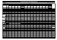
7. Maintenance Standards 7-1 Engine Maintenance Item Category Engine Type Model Cylinder Blower Model mm (in.) Piston Diameter (Skirt) mm (in.) Top mm (in.) 2nd mm (in.) Piston Pin Hole mm (in.) Clearance Between mm (in.) Piston and Cylinder Clearance Between Piston Groove and Piston Ring Top 2nd Fitting Between Piston Pin and Piston Pin Hole Piston Ring - Bore Piston Ring Groove Width Piston Unit - - mm (in.) mm (in.) mm (in.) End Gap at Cylinder mm (in.
7.
8. Troubleshooting 8-1 Engine does not start Remove the spark plug from the cylinder. Put the spark plug on the outside of the cylinder. Pull the recoil starter knob, and check whether sparks arise in the spark gap or not. Trouble Probable Cause Countermeasure No spark in the spark plug. Spark plug 1. Wet spark plug electrodes Make them dry. 2. Carbon deposited on the electrodes 3. Insulation failure by insulator damage Clean. Replace. 4. Improper spark gap Adjust to 0.6~0.7 mm (0.023~0.028 in.).
8. Troubleshooting 8-4 Lack of output power or unstable revolution Trouble Probable Cause Compression is 1. Air is entering at fuel pipe joints, etc normal and no misfire. 2. Air is entering at intake tube joint or carburetor joint 3. Water in fuel 4. Piston is starting to seize Overheating Replace gasket or tighten screws. Replace with clean fuel. Filing of seized surface with fine files. 5. Muffler choked with carbon Clean. 1. Fuel too lean Adjust carburetor. 2.
Printed in Japan 0901 SY – 015