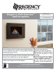
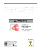
Regency P33 Sunrise™ Gas Fireplace Owners & Installation Manual MODEL: P33S-NG4 Natural Gas P33S-LP4 Propane www.regency-fire.com WARNING: FOR YOUR SAFETY If the information in these instructions are not followed exactly, What to do if you smell gas: Do not try to light any appliance a fire or explosion may result causing property damage, Do not touch any electrical switch: personal injury or loss of life. do not use any phone in your FOR YOUR SAFETY building.
To the New Owner: Congratulations! You are the owner of a state-of-the-art Gas Fireplace by REGENCY®. The P33 Sunrise™ has been designed to provide you with all the warmth and charm of a fire at the flick of a switch. The model P33 Sunrise™ has been approved by Warnock Hersey for both safety and efficiency. As it also bears our own mark, it promises to provide you with economy, comfort and security for many trouble free years to follow.
MANUFACTURED MOBILE HOME REQUIREMENTS INFORMATION FOR MOBILE/MANUFACTURED HOMES AFTER FIRST SALE This Regency® product has been tested and listed by Warnock Hersey as a Direct Vent Wall Furnace to the following standards: VENTED GAS FIREPLACE HEATERS ANSI Z21.88a-2007 / CSA 2.33a-2007 and GAS-FIRED APPLIANCES FOR USE AT HIGH ALTITUDES CAN / CGA 2.17-M91.
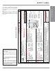
TABLE OF CONTENTS SAFETY LABEL Copy of Safety Decal .....................................................5 REQUIREMENTS MA Code - CO Detector.................................................6 DIMENSIONS Unit Dimensions ............................................................7 INSTALLATION Important Message ......................................................8 Before You Start ............................................................8 General Safety Information...................................
For the State of Massachusetts, flexible connectors shall not exceed 36 inches in length. The State of Massachusetts requires the installation of a carbon monoxide alarm in accordance with NFPA 720 and a CO alarm with battery back up in the same room where the gas appliance is installed. Model/Modele: P33S-NG4 WC WC WC DMS Btu/h Btu/h ft/pi Pression d'allimentation minimum Pression a la tubulure d'échappement élevée Pression a la tubulure d'échappement basse Grandeur de l'injecteur (3.
REQUIREMENTS MA Code - CO Detector (for the State of Massachusetts only) INSTALLATION 5.08: Modifications to NFPA-54, Chapter 10 (2) Revise 10.8.
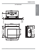
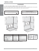
DIMENSIONS UNIT DIMENSIONS INSTALLATION Regency P33 SunriseTM Gas Fireplace 7
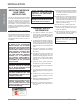
INSTALLATION INSTALLATION IMPORTANT MESSAGE SAVE THESE INSTRUCTIONS The P33 Sunrise™ Fireplace must be installed in accordance with these instructions. Carefully read all the instructions in this manual first. Consult the "authority having jurisdiction" to determine the need for a permit prior to starting the installation. It is the responsibility of the installer to ensure this fireplace is installed in compliance with manufacturers instructions and all applicable codes.
INSTALLATION INSTALLATION CHECKLIST 2) If required, adjusting the primary air to ensure that the flame does not carbon. First allow the unit to burn for 15-20 min. to stabilize. 5) The P33 Sunrise™ Gas Fireplace is approved for alcove installations, see "Clearances" section for details. CAUTION: Any alteration to the product that causes sooting or carboning that results in damage is not the responsibility of the manufacturer.
INSTALLATION CLEARANCES INSTALLATION The clearances listed below are Minimum distances unless otherwise stated: A major cause of chimney related fires is failure to maintain required clearances (air space) to combustible materials. It is of the greatest importance that this fireplace and vent system be installed only in accordance with these instructions. WARNING Fire hazard is an extreme risk if these clearances (air space) to combustible materials are not adhered to.
INSTALLATION MANTEL CLEARANCES INSTALLATION Due to the extreme heat this fireplace emits, the mantel clearances are critical. Combustible mantel clearances from top of front facing are shown in the diagram on the right. Note: A non-combustible mantel may be installed at a lower height if the framing is made of metal studs covered with a non-combustible board. Note: Ensure the paint that is used on the mantel and the facing is "heat resistant" or the paint may discolour.
INSTALLATION INSTALLATION FRAMING & FINISHING 1) Determine the total thickness of facing material (e.g. drywall, wood plus ceramic tiles) to allow the finished surface to be flush with the front of the unit. Total facing thickness can vary from 1/2" (13mm) to 1-1/4" (32mm) thick. NOTE: Facing material may not protrude beyond unit, otherwise the optional accesories will not be able to be mounted to the unit. Install Side Nailing Strips, and Top Facing Support before unit is slipped into position.
INSTALLATION FRAMING DIMENSIONS INSTALLATION M I Top Header Wood, drywall or other facing. 10" (254mm) dia. Hole through wall Vent. H I G J NOTE: If this is an outside corner, the minimum distance between the vent and the outside corner is 6" (15cm) with AstroCap termination cap or 12" (30cm) with Rigid Vent termination cap.
INSTALLATION INSTALLATION UNIT ASSEMBLY PRIOR TO INSTALLATION The Top Facing Support, the Side Nailing Strips and the 2 Top Standoffs must be correctly positioned and attached to the top before the unit is put into position. Top Standoff Assembly The top standoffs are shipped in a flat position and must be pulled up and bent into the correct shape. 1) Remove the standoffs from on top of the firebox by undoing the screws. 2) Take each standoff and bend into the correct shape.
INSTALLATION EXTERIOR VENT TERMINATION REQUIREMENTS INSTALLATION Minimum Clearance Requirements Canada1 USA2 A Clearance above grade, veranda, porch, deck, or balcony 12"(30cm) 12"(30cm) B Clearance to window or door that may be opened 12"(30cm) 9" (23cm) C Clearance to permanently closed window * * D Vertical clearance to ventilated soffit located above the terminal within a horizontal distance of 2 feet (61cm) from the center line of the terminal (check with the local code) 18"(46cm) 18
INSTALLATION REGENCY® DIRECT VENT FLEX SYSTEM INSTALLATION Horizontal Terminations Only This venting system, in combination with the P33S-4 Direct Vent Gas Fireplace, have been tested and listed as a direct vent heater system by Warnock Hersey. The location of the termination cap must conform to the requirements in the "Exterior Vent Terminal Locations" Section . Regency® Direct Vent Flex Termination Kit (Part # 946-513) includes all the parts needed to install the P33S-4 with a maximum run of 2 feet.
INSTALLATION RIGID PIPE VENTING SYSTEMS Horizontal or Vertical Terminations 1 1 1 1 1 AstroCap Horizontal Termination Cap 45o Elbow Rigid Pipe Adaptor Wall Thimble Length of pipe to suit wall thickness (see chart) For siding other than vinyl, furring strips may be used, instead of the vinyl siding standoff, to create a level surface to mount the vent terminal. The Terminal must not be recessed into siding.
INSTALLATION 4" X 6-5/8" RIGID PIPE CROSS REFERENCE CHART INSTALLATION Components from different Manufacturers may not be mixed. Not all Rigid Pipe components are available directly from FPI.
INSTALLATION Description Simpson Selkirk Direct Vent Pro® Direct Temp™ American Metal Products® Metal-Fab™ Security ICC Excel Sure Seal Secure- Vent® Direct Attic Insulation Shield 12” 46DVA-IS N/A@ FPI N/A 4DAIS12 N/A SV4RSA N/A Attic Insulation Shield - Cold Climates 36” N/A N/A 4DAIS12 N/A N/A TM-4AS Basic Horizontal Termination Kit (A) Disc.
INSTALLATION RIGID PIPE VENTING ARRANGEMENTS INSTALLATION Vertical Terminations (Propane & Natural Gas) The shaded area in the diagram shows all allowable combinations of straight vertical and offset to vertical terminations, using one 90o elbow, with rigid pipe vent systems for Propane and Natural Gas. • • • • Unit must be raised 1". Firestops are required at each floor level and whenever passing through a wall. Maintain clearances to combustibles. Vent must be supported at offsets.
INSTALLATION VERTICAL TERMINATION WITH CO-LINEAR FLEX SYSTEM INSTALLATION Masonry chimneys may take various contours which the flexible liner will accommodate. However, keep the flexible liner as straight as possible, avoid unnecessary bending. THE APPLIANCE MUST NOT BE CONNECTED TO A CHIMNEY FLUE SERVING A SEPARATE SOLID FUEL BURNING APPLIANCE. The Air Intake pipe must be attached to the inlet air collar of the termination cap.
INSTALLATION VENTING ARRANGEMENTS - VERTICAL TERMINATIONS Horizontal Distance (Feet) Horizontal Distance (Feet) 30' (9.1m) Max. 8' (2.4m) Min. 30” (762mm) 30” (762mm) 8' (2.4m) Min. 30' (9.1m) Max. 30 2’ (51mm) max. Vertical Height (feet) 8' (2.4m) Min. 30' (9.1m) Max.
INSTALLATION RIGID PIPE VENTING ARRANGEMENTS This diagram shows all allowable combinations of vertical runs with horizontal terminations, using one 45o and one 90o elbow (two 45o elbows equal one 90o elbow). Note: Must use optional rigid pipe adaptor (Part # 510-994) when using rigid pipe vent systems.
INSTALLATION INSTALLATION Horizontal Venting with Two (2) 90o Elbows Horizontal Venting with Three (3) 90o Elbows One 90o elbow = Two 45o elbows. One 90o elbow = Two 45o elbows. Option V H + H1 A) 1' Min. 3' Max. B) 2' Min. 4' Max. C) 3' Min. 5' Max. D) 4' Min. 6' Max. E) 5' Min. 7' Max. F) 6' Min. 8' Max. With these options, maximum total pipe length is 30 feet with minimum of 6 feet total vertical and maximum 8 feet total horizontal. Option H V H+H1+H2 A) 1' Max. 1' Min.
INSTALLATION Horizontal Venting with Three (3) 90o Elbows INSTALLATION One 90o elbow = Two 45o elbows. Option V H V+V1 H+H1 A) 2' Min. 1' Max. 3' Min. 4' Max. B) 3' Min. 2' Max. 4' Min. 5' Max. C) 4' Min. 3' Max. 6' Min. 6' Max. D) 5' Min. 4' Max. 8' Min. 7' Max. E) 6' Min. 5' Max. 10' Min. 8' Max. F) 7' Min. 6' Max. 12' Min. 9' Max. With these options, maximum total pipe length is 30 feet with minimum of 12 feet total vertical and maximum 9 feet total horizontal.
INSTALLATION Vertical Venting with Three (3) 90o Elbows INSTALLATION One 90o elbow = Two 45o elbows. Option A) B) C) D) E) H 1' Max. 2' Max. 3' Max. 4' Max. 5' Max. V 1' Min. 2' Min. 3' Min.' 4' Min. 5' Min. H + H1 3' Max. 4' Max. 5' Max. 6' Max. 7' Max. V + V1 3' Min. 5' Min. 7' Min. 9' Min. 11' Min. With these options, max. total pipe length is 30 feet with min. of 11 feet total vertical and max. 7 feet total horizontal. Please note min. 1 foot between 90 o elbows is required.
INSTALLATION UNIT INSTALLATION WITH HORIZONTAL TERMINATION b) Horizontal runs of vent must be supported every three feet. Wall straps are available for this purpose. 1) Set the unit in its desired location. Check to determine if wall studs or roof rafters are in the way when the venting system is attached. If this is the case, you may want to adjust the location of the unit. Rough in the gas preferably on the right side of the unit and the electrical (junction block is on the left side) on the left.
INSTALLATION INSTALLATION 8) Slide the appliance and vent assembly towards the wall carefully inserting the vent pipe into the vent cap assembly. It is important that the vent pipe extends into the vent cap sufficient distance so as to result in a minimum pipe overlap of 1-1/4 inches. Secure the connection between the vent pipe and the vent cap 3 sheet metal screws. 4) Assemble the desired lengths of pipe and elbows.
INSTALLATION PILOT ADJUSTMENT P33S-NG4 System Data Note: If you have an incorrect flame pattern, contact your FPI dealer for further instructions. Conversion Kit# 434-970 (NG to LP) The appliance must be isolated from the gas supply piping system by closing its individual For 0 to 4500 feet altitude manual shut-off valve during any pressure Burner Inlet Orifice Sizes: #47 testing of the gas supply piping system at test pressures equal to or less than 1/2 psig. (3.45 Max. Input Rating 17,000 Btu/h kPa).
INSTALLATION CONVERSION KIT# 434 - 970 FROM NG TO LP For P33 Sunrise™ Using SIT 820 NOVA Gas Valve INSTALLATION THIS CONVERSION MUST BE DONE BY A QUALIFIED GAS FITTER IF IN DOUBT DO NOT DO THIS CONVERSION !! 6) Unscrew the pilot orifice with the Allen key and replace with the LPG pilot orifice in the kit and replace pilot cap. (See Diagram 6) Each Kit contains one LPG Conversion Kit # 434-970 LPG Conversion Kit Contains: Qty.
INSTALLATION 9) Turn control knob to the “OFF” position. 10) Remove the black protection cap by hand from the high-low knob (Fig.1). 14) Using the Allen wrench as shown in Fig.4, rotate the screw clockwise until snug, do not overtighten. 17) Attach the label "This unit has been converted to LPG" near or on top of the serial # decal. INSTALLATION 18) Replace yellow "NG" label with red "LPG" label. 19) Check for gas leaks. 20) Check inlet and outlet pressures. 21) Check operation of flame control.
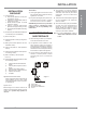
INSTALLATION INSTALLATION DC SPARK BOX BATTERY REPLACEMENT DC SPARK BOX REPLACEMENT 1) Remove the faceplate by lifting it up off the flush door. 1) Shut the power off. 2) Remove the battery cover from the DC Spark Box. 2) Remove the faceplate by lifting it up off flush door. 3) Remove the AA battery and replace with a new one. 3) Remove the screw securing the control assembly plate to the left side of fire box (Diagram 1).
INSTALLATION Optional WALL THERMOSTAT Note: Preferable if the thermostat is installed on an interior wall. Regency® offers an optional programmable thermostat but any 250-750 millivolt rated nonanticipator type thermostat that is CSA, ULC or UL approved may be used. CAUTION Do not wire millivolt wall thermostat wires to 120V wire. Thermostat Wire Table Recommended Maximum Lead Length (Two-Wire) When Using Wall Thermostat (CP-2 System) Wire Size Max. Length 14 GA. 50 Ft. 16 GA. 32 Ft. 18 GA. 20 Ft.
INSTALLATION The burner aeration is factory set but may need adjusting due to either the local gas supply or altitude. Open the air shutter for a blue flame or close for a more yellow flame. CAUTION: Carbon will be produced if air shutter is tightly closed. Minimum Air Shutter Opening: NG LP 1/16" 1/4" Note: Any damage due to carboning resulting from improperly setting the aeration controls is NOT covered under warranty.
INSTALLATION GT REMOTE WIRING DIAGRAM IMPORTANT INSTALLATION NOTE: INSTALLATION The SIT Proflame GT REMOTE Receiver must be placed inside the supplied (Low Voltage) junction type wall box and installed into the wall only. DO NOT INSTALL WITHIN THE CONFINES OF THE FIREPLACE. Wall Mounting 1. Add two male spade connectors to the end of the 10 foot 2-wire harness (Black & Red) installed with P33S. 2. Install the J-Box to the framing, at desired location within 10ft from fireplace. 3.
INSTALLATION INSTALLATION INSTALLING THE OPTIONAL FAN 120 Volt AC power is needed for the fan switch and blower. The fan can be hard wired if desired. The grounded duplex receptacle should be installed into the supplied receptacle box by a qualified electrician. The neutral (wider) slot of the polarized receptacle should be at the top. 6) Attach the fan control box to the Control Plate. (Diagram 3 & 4) Fan Control Box Unit must be grounded at all times.
INSTALLATION OPTIONAL REFLECTIVE PANEL INSTALLATION Before installation, panels must be handled and cleaned as per instructions noted below: • Stainless panels must be inspected for scratches and dimples prior to installation. All claims to be recorded at this time. Claims for damage after installation will not receive consideration. INSTALLATION Stainless Steel Panels Black Enamel Panels • Black Enamel panels must be inspected for scratches and dimples prior to installation.
INSTALLATION INSTALLATION GLASS CRYSTAL INSTALLATION ON BURNER Spread the supplied Glass Crystals (or optional Ceramic Spa Stones) evenly over the burner. Ensure the crystals (stones) do not overlap too much as this will effect the flame pattern. NOTE: When installing, use either the supplied Glass Crystals or optional Ceramic Spa Stones - DO NOT combine the two. Only the supplied approved Cobalt Blue Glass or optional Ceramic Spa Stones (50 pieces recommended) are to be used with this fireplace.
INSTALLATION STANDARD FLUSH DOOR INSTALLATION INSTALLATION The standard flush door comes with a black frame. To install the frame and glass door, simply hook the top door flange onto the top of the unit and swing the door towards the unit, diagram 1. Be careful that the glass gasket does not roll up; there must be a gap between the gasket and the door lip to ensure that the door sits securely on the unit. See Diagram 2.
INSTALLATION FACEPLATE INSTALLATION 3) Loosen 4 phillips head screws located inside firebox, for screw locations see Diagram 4. Install mounting frame and retighten screws.
INSTALLATION 6) Hook the flange on the faceplate over the top of the flush door and gently lower the faceplate into place until it rests against the faceplate supports as shown in Diagrams 7 & 8.
OPERATING INSTRUCTIONS OPERATING INSTRUCTIONS LIGHTING PROCEDURE 1) Read and understand these instructions before operating this appliance. IMPORTANT To ignite or reignite the pilot, you must first remove the glass door. 2) Check to see that all wiring is correct and enclosed to prevent possible shock. 3) Check to ensure there are no gas leaks. 4) Make sure the glass in the glass door frame is properly positioned. Never operate the appliance with the glass removed.
OPERATING INSTRUCTIONS COPY OF LIGHTING PLATE INSTRUCTIONS FOR YOUR SAFETY READ BEFORE LIGHTING This appliance must be installed in accordance with local codes, if any; if none, follow the National Fuel Gas Code, ANSI Z223.1/NFPA 54, or Natural Gas and Propane Installation Codes, CSA B149.1. (Australia: AS5601-2004, New Zealand: NZS 5261) WARNING: If you do not follow these instructions exactly, a fire or explosion may result causing property damage, personal injury or loss of life.
MAINTENANCE MAINTENANCE INSTRUCTIONS GENERAL VENT MAINTENANCE 1) Always turn off the gas valve before cleaning. For relighting, refer to lighting instructions. Keep the burner and control compartment clean by brushing and vacuuming at least once a year. Conduct an inspection of the venting system semi-annually. Recommended areas to inspect as follows: 2) Clean appliance and door with a damp cloth (never when unit is hot). Never use an abrasive cleaner.
MAINTENANCE VALVE TRAY REPLACEMENT REMOVING VALVE 1) Shut off the gas supply. 2) Remove the faceplate. 3) Open the flush door and remove the door. 4) Remove the burner assembly by removing the two Phillips head screws and then lift the burner assembly out. (See Diagram 1) 7) Disconnect the inlet gas line. 8) Disconnect the 2 TP wires and the 2 TH wires from the valve (Refer to wiring diagram on page 33).
PARTS LIST MAIN ASSEMBLY Part # Description Part # 434-907 434-908 Reflective Panel Stainless Steel (Optional) Reflective Panel Black Enamel (Optional) 1) 2) 3) 4) * * * * Panel Rear P33S (SS / Black Enamel) Panel Top P33S (SS / Black Enamel) Panel Side Left P33S (SS / Black Enamel) Panel Side Right P33S (SS / Black Enamel) 8) 434-516 434-516BL 434-516R 434-517 Faceplate Assembly Black Faceplate Assembly Painted Blue Faceplate Assembly Painted Red Faceplate Assembly Stainless Steel 10) 434-033 M
WARRANTY Regency® Fireplace Products are designed with reliability and simplicity in mind. In addition, our internal Quality Assurance Team carefully inspects each unit thoroughly before it leaves our facility. FPI Fireplace Products International Ltd. is pleased to extend this limited lifetime warranty to the original purchaser of a Regency® Product. This warranty is not transferable.
Regency® fireplaces are designed with reliability and simplicity in mind. In addition, our internal Quality Assurance Team carefully inspects each unit thoroughly before it leaves our door. Regency Fireplace Products is pleased to extend this Limited Lifetime Warranty to the original purchaser of a Regency® Product. See the inside back cover for details. Register your Regency® online at http://www.regency-fire.