MSK-8400BL-18 MSK-8420BL-18 Industrial Sewing Machine Instruction Manual
CONTENTS Operation instruction 1. Brief introduction 1 2. Main specifications 1 3. Machine installation and operation preparation 1 1. Machine installation 1-3 2. Operation preparation and notice before running 3-4 4. Machine operation 5-6 1. Coordination among needle, thread and materials 5 2. Install the needle 5 3. Winding the bobbin thread 5. Machine adjustment 1. Adjust the needle thread tension and bobbin thread tension 2. Adjust the pressure of presser foot 3.
Operation instruction
MSK-8420BL-18 machine adopts straight double needle and two vertical auto-lubricating hooks for thread looping, sliding lever for thread take up to form two lines of lockstitch seam. The upper and lower shafts are supported by needle bearing and driven by toothed belt, plunger oil pump lubrication system, compound feed mechanism of feed dog, walking foot and needle, so even if for long stitch length or sewing long materials, it can deal with them freely. .
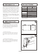
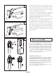
3 C A B 1.4 Install the presser foot lifting controller (Fig. 3) First connect the chain B with presser foot lift lever C by hooks A, then install the pedal assembly D on the rung of the stand, move the controller E leftward or rightward to make the chain in one line, fix it with bolt and nut, finally connect the hook with the . controller E. (An automatic presser foot lifter is also available, please refer to parts manual Part 7. "Knee lifter and winding components") . E D 4 1.
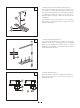
1.7 Connecting the clutch lever to the pedal (Fig. 6) A. The optimum tilt angle of pedal against floor is approx. 20 30 . . B. Adjust the clutch of motor so that the clutch lever C and draw bar B run in line. . C. The machine hand wheel should rotate counter-clockwise for normal sewing when view from opposite side of balance wheel. The motor should rotate in the same direction. The rotation can be reversed by reversing the plug of motor (turn over 180 ) . D.
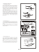
B. When the machine starts for initial time or reuse 9 after a long time, the proper oil amount should be filled in the sections of machine shown by arrows in Fig. 8,9. When it is in operation, please observe the oil sparking in oil screen to check the oil condition. . C. When a new machine starts running, for extending its lift, please run at a medium and low speed (1000s.p.m) for about a month and then raise the speed gradually. . D.
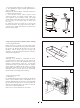
3. Winding the bobbin thread 12 3.1 The method of winding Insert the bobbin B into winder shaft, threading the thread A to upper and lower holes of pin E, then to thread tension disc F, draw the thread tip and wind thread several circles around bobbin B, put the winding lever D into bobbin B, then it can automatic winding when sewing. (If only winding, not sewing, . please lift the presser foot.) Please don't overfill the bobbin thread, otherwise the thread will loosen down from the bobbin.
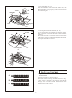
3.4 Placing bobbin (Fig. 15) Note: when bobbin is placed into the bobbin case, the thread should be wound properly in the correct direction shown in the figure. . 15 Thread Sliding plate Hook Hook Sliding plate 16 3.5 Drawing thread from the bobbin (Fig. 16) A. Draw the thread end to bobbin slot shown in the figure, and pull it out down through the inner bobbin . stop piece. B. Hold the thread end with left hand, turn the hand wheel slowly and get the bobbin thread, then draw them .
A. If the stitch seam shows as Fig. 17B, indicates 18 that the needle thread tension is too tight or the bobbin thread tension is too loose. Please turn the thread tension nut counter-clockwise to release the Loosen needle thread pressure; or turn the bobbin lace adjusting screw with a screwdriver to increase the bobbin thread tension.( See Fig. 18,19) . Tighten Adjusting screw B. If the needle thread tension is too loose or the bobbin thread tension is too tight shown as Fig. 17C.
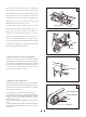
3.2 How to reset the safety clutch device (Fig.22) 22 A. While press down the button on the bed surface with left hand, turn the hand wheel slowly with right hand in . the direction shown in Fig. 22 (clockwise). B. When the stopper brakes the hand wheel, more strength is needed to turn the balance wheel to reset the . safety clutch device. . C. Release the button. D. So the resetting is OK and put the bobbin into hook. . (See Fig.15) Handwheel Button White mark 3.
3.5 Adjust the vertical stroke of presser foot (Fig. 25) When stitch on the very elastic materials or the thickness of sewing materials changes, the adjustment should be done in the following order: . . A. Loosen the special stud. B. When the central line distance between the special stud and the presser foot lifting rear crank becomes shorter, the vertical stroke of presser foot will become longer, on the contrary, the distance becomes longer, the stroke will become shorter. . C.
Parts manual
10 39 35 26 27 31 30 29 32 33 34 25 24 36 28 18 23 22 38 21 20 17 16 40 37 15 19 66 43 42 65 41 14 10 9 67 13 12 57 58 14 55 61 60 3 68 11 62 59 63 64 53 52 4546 4745 49 56 54 44 4 5 1 6 2 8 7 51 48 50 13 12 1.
1.MSK-8420BL-18 machine casting components No. 1 2 3 4 5 6 7 8 9 10 11 12 13 14 15 16 17 18 19 20 21 22 23 24 25 26 27 28 29 30 31 32 33 34 35 36 37 38 39 40 41 42 43 43WF1-001 43WF1-002 43WF1-003B 43WF1-004B 1WF1-015 1WF1-016 1WF1-017 1WF1-011 22T1-007 1WF1-032 1WF1-038 1WF1-039 1WF1-019 1WF1-030 1WF1-027 1WF1-028 1WF1-003 1WF1-004 Qt.
12 39 35 26 27 31 30 29 32 33 34 25 24 36 28 18 23 22 38 21 20 17 16 40 37 15 19 66 43 42 65 41 14 10 9 67 13 12 57 58 14 55 61 60 3 68 11 62 59 63 64 53 52 4546 4745 49 56 54 44 4 5 1 6 2 8 7 51 48 50 13 12 1.
1.MSK-8420BL-18 machine casting components Name Qt. No.
14 37 33 24 25 29 28 27 30 31 32 23 22 26 20 18 36 19 17 16 21 41 40 15 63 38 35 34 39 14 10 9 64 13 12 55 56 14 53 59 58 3 65 11 60 57 42 54 52 61 62 51 47 50 43 4445 43 4 5 1 6 2 8 7 49 46 48 13 12 2.
No. Name Part number Qt.
16 37 33 24 25 29 28 27 30 31 32 23 22 26 20 18 36 19 17 16 21 41 40 15 63 38 35 34 39 14 10 9 64 13 12 55 56 14 53 59 58 3 65 11 60 57 42 54 52 61 62 51 47 50 43 4445 43 4 5 1 6 2 8 7 49 46 48 13 12
Name Qt. No.
18 14 41 42 43 39 40 35 37 38 11 8 54 13 14 15 16 36 45 44 33 6 7 52 4 3 19 17 2 46 1 34 21 22 10 55 56 23 49 32 29 48 47 9 5 8 24 25 26 27 5150 12 20 13 18 53 31 30 28
No. Part number Name Qt.
1 2 3 5 6 7 4 8 9 10 12 13 30 29 28 27 11 14 15 16 17 18 19 20 26 22 38 40 43 42 44 43 45 42 46 47 48 49 1 21 25 24 23 MSK-8420BL-18 33 34 32 41 39 36 37 31 35 MSK-8400BL-18 33 34 35 75 76 74 73 72 70 69 59 61 60 68 59 63 53 52 51 50 77 78 79 45 80 71 67 66 64 65 54 20 57 56 62 58 45 57 56 55 54
No.
1 2 3 5 6 7 4 8 9 10 12 13 30 29 28 27 11 14 15 16 17 18 19 20 26 22 38 40 43 42 44 43 45 42 46 47 48 49 1 21 25 24 23 MSK-8420BL-18 33 34 32 41 39 36 37 31 35 MSK-8400BL-18 33 34 35 75 76 74 73 72 70 69 59 61 60 68 59 63 53 52 51 50 77 78 79 45 80 71 67 66 64 65 54 22 57 56 62 58 45 57 56 55 54
No. Name Part number 41 1WF5-022 42 1WF5-027 43 1WF5-028 44 Qt.
7 8 9 10 6 5 11 4 12 13 14 3 15 16 17 18 2 28 27 29 28 19 20 21 26 24 1 23 22 25 31 32 33 34 35 36 37 42 43 44 45 46 47 48 50 51 52 40 39 38 41 49 30 53 54 24
Qt. No.
2 3 5 4 6 8 10 7 2 9 12 16 1 15 18 13 19 11 29 30 28 26 27 14 17 24 20 24 25 22 2 23 21 26
No. Name Part number Qt. Remark 1 1WF4-025 Stitch length adjusting rocking lever 1 2 1WF4-030 Screw 5 SM15/64" 28/8.5 3 1WF4-026 Set screw 1 SM15/64" 28/12 4 1WF4-014 Stitch length link 1 5 1WF4-028 Eccentric shaft 1 6 1WF4-046 Reverse feed shaft 1 7 1WF4-047 Reverse feed crank 1 8 1WF4-027 Screw 1 SM15/64" 28/13 9 1WF4-021 Screw 1 SM15/64" 40/10.
23 22 14 19 15 17 16 18 25 24 2 21 26 3 20 11 28 4 29 27 12 6 7 5 13 8 1 9 10 50 44 31 30 37 49 32 33 34 36 52 35 48 47 46 45 51 44 43 38 42 41 Automatic presser foot lifter components 56 40 39 55 57 54 58 59 36 28 53
No.
3 4 6 7 40 41 11 12 13 14 15 2 47 16 10 9 5 1 8 46 21 48 20 49 21 26 20 16 17 18 42 19 20 21 23 44 43 45 25 24 23 22 26 39 27 28 16 38 23 37 36 23 35 34 16 30 31 30 29 32 33
No.
6 1 7 8 3 2 4 18 9 5 10 11 16 12 19 13 20 21 14 22 17 32 15
No. Name Part number Qt. Remark 1 33TF-010 Parts bag 1 2 22T9-007F1 Casting hinge 2 3 22T9-007F2 Casting hinge cushion 2 4 22T9-009 Casting cushion (big) 2 5 22T9-010 Casting cushion 2 6 1WF2-065 Bobbin 4 7 33TF-011 Oil pot 1 8 33TF-016 V-belt 1 'O' type 1050 9 1F-009 Needle 1 bag DP 17 23# 10 1F-011 Hexagon wrench 1 S=2.
www.reliablecorporation.