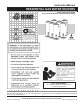
Instruction Manual RESIDENTIAL GAS WATER HEATERS DIRECT VENT GAS MODELS NOT FOR USE IN MANUFACTURED (MOBILE) HOMES GAMA certification applies to all residential gas water heaters with capacities of 20 to 100 gallons with input rating of 75,000 BTU/Hr. or less. • For Your Safety • AN ODORANT IS ADDED TO THE GAS USED BY THIS WATER HEATER. ALL TECHNICAL AND WARRANTY QUESTIONS: SHOULD BE DIRECTED TO THE LOCAL DEALER FROM WHOM THE WATER HEATER WAS PURCHASED.
SAFE INSTALLATION, USE AND SERVICE Your safety and the safety of others is extremely important in the installation, use and servicing of this water heater. Many safety-related messages and instructions have been provided in this manual and on your own water heater to warn you and others of a potential injury hazard. Read and obey all safety messages and instructions throughout this manual.
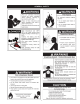
GENERAL SAFETY 3
TABLE OF CONTENTS SAFE INSTALLATION, USE AND SERVICE . . . . . . . . . . . . . 2 GENERAL SAFETY . . . . . . . . . . . . . . . . . . . . . . . . . . . . . . . . 3 TABLE OF CONTENTS . . . . . . . . . . . . . . . . . . . . . . . . . . . . . 4 INTRODUCTION . . . . . . . . . . . . . . . . . . . . . . . . . . . . . . . . . . . 4 Preparing for the installation . . . . . . . . . . . . . . . . . . . . . . . 4 INSTALLATION REQUIREMENTS FOR THE COMMONWEALTH OF MASSACHUSETTS . . . . . . . . . . . . .
INSTALLATION REQUIREMENTS FOR THE COMMONWEALTH OF MASSACHUSETTS For all side wall terminated, horizontally vented power vent, direct vent, and power direct vent gas fueled water heaters installed in every dwelling, building or structure used in whole or in part for residential purposes, including those owned or operated by the Commonwealth and where the side wall exhaust vent termination is less than seven (7) feet above finished grade in the area of the venting, including but not limited to decks and porch
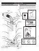
TYPICAL INSTALLATION GET TO KNOW YOUR WATER HEATER REPLACEMENT PARTS Replacement parts may be ordered through authorized servicers or distributors. When ordering parts, provide complete model and serial numbers (see rating plate), quantity and name of part desired (as listed in Figure 1). Standard hardware items may be purchased locally.
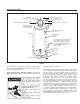
MIXING VALVE USAGE NON-SCALD TEMPERING VALVE TEMPERED POTABLE WATER SHUT-OFF VALVE COLD WATER INLET NON-TEMPERED WATER SUPPLY NON-TEMPERED WATER RETURN SUGGESTED PIPING ARRANGEMENT FOR TOP CONNECTIONS TEMPERATURE-PRESSURE RELIEF VALVE GAS SUPPLY DISCHARGE PIPE (DO NOT CAP OR PLUG) CERTAIN MODELS ARE EQUIPPED WITH SIDE PLUMBING CONNECTIONS FOR SPACE HEATING. THE HOT AND COLD FITTING ASSEMBLIES (PART # 9001262) CAN BE ORDERED THROUGH THE MANUFACTURER.
LOCATING THE NEW WATER HEATER FACTS TO CONSIDER ABOUT THE LOCATION • Carefully choose an indoor location for the new water heater, because the placement is a very important consideration for the safety of the occupants in the building and for the most economical use of the appliance. This water heater is not for use in manufactured (mobile) homes or outdoor installation. Sensors mounted in the drain pan that turn off the water supply to the entire home when water is detected in the drain pan.
Confined Space is a space whose volume is less than 50 cubic feet per 1,000 Btu per hour (4.8 cm per kW) of the aggregate input rating of all appliances installed in that space. VENT TERMINATION Before installing water heater determine placement of vent termination. Make certain to observe vent location limitation, see Figures 3, 4 & 12. INSULATION BLANKETS Minimum clearances between the water heater and combustible and noncombustible construction are: 0 in. (0mm) from sides, 0 in. (0mm) from back, 4 in.
INSTALLING THE NEW WATER HEATER REQUIRED ABILITY INSTALLATION OR SERVICE OF THIS WATER HEATER REQUIRES ABILITY EQUIVALENT TO THAT OF A LICENSED TRADESMAN IN THE FIELD INVOLVED. PLUMBING, AIR SUPPLY, VENTING AND GAS SUPPLY ARE REQUIRED. INSPECT SHIPMENT This water heater shall not be connected to any heating systems or component(s) used with a non-potable water heating appliance. There may be hidden damage caused in transit. Check to be certain all parts of the venting system, as listed below, are present.
FIGURE 6 HOT WATER OUTLET COLD WATER INTLET Fit pipe insulation over the incoming cold water line and the hot water line. Make sure that the insulation is against the top cover of the heater. Fit T & P valve insulation over valve. Make sure that the insulation does not interfere with the lever of the T & P valve. SHUTOFF VALVE UNION 3/4” SWEAT FITTING UNION 3/4” SWEAT FITTING Secure all insulation using tape.
distance below the structural floor. Be certain that no contact is made with any live electrical part. The discharge opening must not be blocked or reduced in size under any circumstances. Excessive length, over 30 ft. (9.14m), or use of more than four elbows can cause restriction and reduce the discharge capacity of the valve, see Figures 5 or 10. 4.
minimum inlet gas pressure shown on the rating plate is that which will permit firing at rated input. All gas piping must comply with local codes and ordinances or with the National Fuel Gas Code ANSI Z223.1/NFPA 54 whichever applies. Copper and brass tubing and fittings (except tin lined copper tubing) shall not be used. If the gas control valve is subjected to pressures exceeding 1/2 psi (3.5 kPa), the damage to the gas control valve could result in a fire or explosion from leaking gas.
FILLING THE WATER HEATER SEDIMENT TRAPS Never use this water heater unless it is completely full of water. To prevent damage to the tank, the tank must be filled with water. Water must flow from the hot water faucet before turning “ON” gas to the water heater. A sediment trap shall be installed as close to the inlet of the water heater as practical at the time of water heater installation.
COMBUSTION AIR AND VENTILATION When determining the installation location for a direct vent water heater, snow accumulation and drifting should be considered in areas where applicable. VENT TERMINAL CLEARANCES The vent system must terminate so that proper clearances are maintained as cited in local codes or the current edition of the National Fuel Gas Code ANSI Z223.
LOCATING CLEARANCE HOLE FOR VENT Cut a clearance hole, approximately 7 in. (178mm) in diameter, through the exterior wall for the vent assembly. The recommended height is 68 in. (1.72m) for 40 gal. models and 76 in. (1.93m) for 50 gal., 50 gal. Hi-Input and 75 gal. models, as measured from the hole center to bottom of water heater. The maximum height recommended is 80 in. (2.03m) or in compliance with Figure 16. Where the wall is combustible and the wall thickness is over 14 in. (356mm), 1 in.
UNCOMPRESSING THE CORRUGATED TUBING STANDARD VENT ARRANGEMENT 3.6 in. (91mm) 2.6 in. (67mm) 17 in. (432mm) MIN.,* 80 in. (2.03m) MAX. 1. Pull the inner corrugated tube towards the water heater and leave some length over the water heater’s center for bending. 2. Pull the outer corrugated tube toward the water heater and leave it 1 in. (25mm) shorter than the inner corrugated tube. 3. Make sure there are two springs evenly spaced at the bend in the tube. 4.
TOP VIEW 90° MAXIMUM BEND FIGURE 23 FIGURE 26 CONDITION 2: Apply hi-temp red silicone (included) around the collar on air manifold box. Pull corrugated vent tube all the way on to collar and secure with one sheet metal screw (approx. 3/4 in. (19mm) up from edge of vent tube. Pull gear clamp past screw and tighten. Where floor joists impede venting, a rise or drop to complete the vent termination is possible. All installations require 1 in. (25mm) clearance to combustibles. Note: A.
FOR YOUR SAFETY READ BEFORE LIGHTING BEFORE LIGHTING: ENTIRE SYSTEM MUST BE FILLED WITH WATER AND AIR PURGED FROM ALL LINES A. This appliance has a pilot which is lit by a piezo-electric • If you cannot reach your gas supplier, call the fire spark gas ignition system. Do not open the inner door of department. the appliance and try to light the pilot by hand. C. Use only your hand to push in or turn the gas control knob. Never use tools. If the knob will not push in or turn B.
TEMPERATURE REGULATION TEMPERATURE REGULATION Time to Produce 2nd & 3rd Degree Burns on Adult Skin Temperature Setting HOT WATER CAN SCALD: Water heaters are intended to produce hot water. Water heated to a temperature that will satisfy space heating, clothes washing, dish washing, and other sanitizing needs can scald and permanently injure you upon contact. Some people are more likely to be permanently injured by hot water than others.
FOR YOUR INFORMATION EXTERNAL DAMAGE THERMAL EXPANSION Do not operate the water heater until it has been fully checked out by a qualified technician, if the water heater: • • • Has been exposed to fire or damage. Displays evidence of sooting. Produces steam or unusually hot water. If the water heater has been flooded it must be replaced.
lines. Contact the local water heater supplier or service agency for further information concerning an Anode Replacement Kit and this chlorination treatment. If the smelly water persists after the anode replacement and chlorination treatment, we can only suggest that chlorination or aeration of the water supply be considered to eliminate the water problem. Do not remove the anode leaving the tank unprotected. By doing so, all warranty on the water heater tank is voided.
MAINTENANCE FOR YOUR SAFETY AND SATISFACTORY OPERATION, IT IS RECOMMENDED THAT THIS HEATER BE CHECKED ONCE A YEAR BY A COMPETENT SERVICE PERSON. a flooded water heater. Do not attempt to repair the unit! It must be replaced! At least once a year a visual inspection should be made of the main burner and the pilot assembly for proper flame characteristics. This can be done by removing the Outer Door and viewing the main burner operation through the Viewport on the Inner Door, see Figure 1.
DRAINING If the heater is to be shut off and exposed to freezing temperatures, it must be drained. Water, if left in the tank and allowed to freeze, will damage the heater. • Turn off the gas and cold water inlet valve to the heater, Figure 1. • Open a nearby hot water faucet and the heater drain valve. • BE CAREFUL TO GRASP THE DRAIN VALVE HANDLE SO THAT THE HAND IS NOT EXPOSED TO HOT WATER. IF DESIRED, A HOSE MAY BE CONNECTED TO THE DRAIN VALVE TO CARRY THE WATER AWAY. The water CAN BE HOT.
Before removing the anode: 1) the tank water should be cool, 2) the cold water shut off valve must be closed, and 3) water pressure must be relieved by opening a nearby faucet. DRAIN VALVE WASHER REPLACEMENT (See Figure 29) 1. Turn “OFF” gas supply to water heater. 2. Follow “Draining” instructions. 3. Turning counterclockwise ( ), remove the hex cap below the screw handle. 4. Remove the washer and put the new one in place. 5.
LEAKAGE CHECKPOINTS SERVICE If a condition persists or you are uncertain about the operation of the water heater contact a service agency. Use this guide to check a “Leaking” water heater. Many suspected “Leakers” are not leaking tanks. Often the source of the water can be found and corrected. If you are not thoroughly familiar with gas codes, your water heater, and safety practices, contact your gas supplier or qualified installer to check the water heater. Read this manual first.
TROUBLESHOOTING GUIDELINES PROBLEM BURNER WILL NOT IGNITE SMELLY WATER BURNER FLAME YELLOWLAZY PILOT WILL NOT LIGHT OR REMAIN LIT POSSIBLE CAUSE(S) 1. 2. 3. 4. 5. 6. 7. 8. 9. Pilot not lit Thermostat set too low No gas Dirt in the gas lines Pilot line clogged Main burner line clogged Defective thermocouple Defective gas control/thermostat Heater installed in a confined area CORRECTION 1. 2. 3. 4. 5. 6. 7. 8. 9. Light pilot Turn temp.
PROBLEM POSSIBLE CAUSE(S) 1. Insufficient secondary air SLOW HOT WATER RECOVERY 2. 3. 4. 5. 6. 7. 8. Flue clogged Low gas pressure Improper calibration Gas control/thermostat set too low Water heater too small Wrong piping connections Wasted hot water 1. Excessive water pressure DRIP FROM RELIEF VALVE THERMOSTAT FAILS TO SHUT OFF COMBUSTION ODORS CONDENSATION 1. Provide ventilation to water heater. Check flue way, flue baffle and burner 2. Clean flue, locate source and correct 3.
NOTES 29
RESIDENTIAL GAS WARRANTY CONDITIONS AND EXCEPTIONS THIS WARRANTY IS APPLICABLE TO THE ORIGINAL OWNER ONLY in accordance with the warranty terms and conditions specified below.
This warranty does not apply to water heaters used to heat pools, whirlpools or hot tubs or used for space heating where its sizing does not conform with specifications of the heating component manufacturer. CLAIM PROCEDURE Any claim under this warranty should be initiated by contacting: This warranty gives you specific legal rights, and you may have other rights which vary under the laws of each state.
500 TENNESSEE WALTZ PARKWAY ASHLAND CITY, TN 37015 Phone: 800-821-2017 • Fax: 800-644-9306 www.reliancewaterheaters.