Installation Instructions and Use & Care Guide RESIDENTIAL GAS WATER HEATERS HIGH EFFICIENCY ATMOSPHERIC VENT GAS WATER HEATER (FLAMMABLE VAPOR IGNITION RESISTANT) FOR SPACE HEATING AND POTABLE WATER HEATING ONLY. NOT FOR USE IN MOBILE HOMES. This water heater complies with ANSI Z21.10.1-current edition regarding the accidental or unintended ignition of flammable vapors, such as those emitted by gasoline. For Your Safety AN ODORANT IS ADDED TO THE GAS USED BY THIS WATER HEATER.
TABLE OF CONTENTS Water Heater Safety ........................................................................................................................................................................... 1-4 Safe Installation, Use and Service ...................................................................................................................................................... 3 Safety Precautions ...........................................................................................
SAFE INSTALLATION, USE AND SERVICE Your safety and the safety of others is extremely important in the installation, use and servicing of this water heater. Many safety-related messages and instructions have been provided in this manual and on your water heater to warn you and others of a potential hazard. Read and obey all safety messages and instructions throughout this manual.
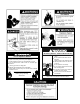
Breathing Hazard - Carbon Monoxide Gas Install vent system in accordance with codes. Do not operate water heater if flood damaged Heater should not be installed for High Altitude operation above 10,100 feet (3,078 m). Do not operate if soot buildup. Fire or Explosion Hazard Do not store or use gasoline or other flammable vapors and liquids in the vicinity of this or any other appliance. Avoid all ignition sources if you smell Natural or LP gas. Do not expose water heater control to excessive gas pressure.
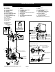
TYPICAL INSTALLATION GET TO KNOW YOUR WATER HEATER - GAS MODELS A B C D E F G H I J Vent Pipe Draft hood Anode (Not Shown) Hot Water Outlet Insulation Gas Supply Piping Manual Gas Shut-off Valve Ground Joint Union Drip Leg (Sediment Trap) Inner Door * INSTALL IN ACCORDANCE WITH LOCAL CODES. * DRIP LEG AS REQUIRED BY LOCAL CODES. * ALL PIPING MATERIALS TO BE SUPPLIED BY CUSTOMERS.
INSTALLING YOUR GAS WATER HEATER A rating plate identifying your water heater can be found on the front of your water heater. When referring to your water heater, always have the information listed on the rating plate readily available. Retain your original receipt as proof of purchase. Important Information About This Water Heater This gas water heater was manufactured to voluntary safety standards to reduce the likelihood of a flammable vapor ignition incident.
Location Requirements If flammable liquids or vapors have spilled or leaked in the area of the water heater, leave the area immediately and call the fire department from a neighbor’s home. Do not attempt to clean the spill until all ignition sources have been extinguished. WARNING Carbon Monoxide Poisoning Hazard WARNING Do not install in a mobile home. Doing so can result in carbon monoxide poisoning and death.
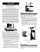
EXHAUST FAN REVERSE FLOW OF GASES IMPORTANT: The water heater should be located in an area where leakage of the tank or connections will not result in damage to the area adjacent to the water heater or to lower floors of the structure. Due to the normal corrosive action of water, the tank will eventually leak after an extended period of time. Also any external plumbing leak, including those from improper installation, may cause early failure of the tank due to corrosion if not repaired.
GAS SUPPLY WARNING Manual Gas Shut-Off Valve Ground Joint Union Install a readily accessible manual shut-off valve in the gas supply line as recommended by the local utility. Explosion Hazard Discharge Pipe (Do Not plug or cap) Check with local utility for minimum height. • Use a new CSA approved gas supply line. 3” Minimum • Install a shut-off valve. Drip Leg • Do not connect a natural gas water heater to an L.P. gas supply. 6” Max. Air Gap Suitable Drain FIGURE 3.
Gas Pipe Capacity Table WARNING WARNING Explosion Hazard Explosion Hazard • Use a new CSA approved gas supply line. • Gas leaks can not always be detected by smell. • Install a shut-off valve. • • Do not connect a natural gas water heater to an L.P. gas supply. Gas suppliers recommend that you use a gas detector approved by UL or CSA. • For more information, contact your gas supplier.
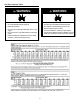
COMBUSTION AIR & VENTILATION TABLE 3 WARNING BTUH Input Minimum Square Feet with 8’ Ceiling Vent must be installed by a qualified technician using the installation instructions. 30,000 188 9 x 21 45,000 281 14 x 20 Examples of a qualified technican include: gas technicians, authorized gas company personel, and authorized service persons.
Attic or crawl spaces cannot be closed and must be properly ventilated to the outside. 12” Max. Permanent openings to the outside or additional rooms within the building Ductwork must be of the same cross-sectional area as the free area of the opening to which they connect. The minimum dimension of rectangular air ducts cannot be less than three inches. The size of each of the two openings is determined by the method in which the air is to be provided.
Alternative Opening Location Gable Vent to Outdoors Install Above Insulation Confined Space 1 sq. in. per 3000 BTUH Confined Space Outlet Air to the Attic 1 sq. in. per 4000 BTUH Inlet Air from the Crawl Space Alternative Air Inlet All Air From Outdoors - Using A Single Permanent Opening FIGURE 8B. Open Foundation Vent 1 sq. in. per 4000 BTUH Vent Pipe System This water heater uses a non-direct, single-pipe vent system to remove exhaust gases created by the burning of fossil fuels.
40 Gallon Water Heaters: NOTE: Reducer flue must be installed on the water heaters above elevation 5,400 Ft. (1,646 m) from sea level. Separate the reducer flue from the draft hood and align the reducer flue on 40 gallon units over top of baffle as shown in Figure 9 (see next paragraph for draft hood installation instructions). used for venting solid fuel appliances or fireplaces.
Figures 10-12 are examples of vent pipe system installations and may or may not be typical for your specific application. Consult the “National Fuel Gas Code”, NFPA 54, ANSI Z223.1-current edition and the guidelines set forth by prevailing local codes. 3 FT. Minimum WATER SYSTEM PIPING Piping Installation Piping, fittings, and valves should be installed according to the installation drawing (Figure 13).
Closed System/Thermal Expansion In a closed system use a thermal expansion tank Hot Water Outlet Cold Water Inlet Valve Pressure Reducing Valve with Bypass Cold Water Supply to Fixture Main Water Supply Temperature and Pressure (T&P) Relief Valve (Optional Top T&P Relief Valve Not Shown) Massachusetts: Install a vacuum relief in cold water line per section 19 MGL 142 As water is heated, it expands (thermal expansion). In a closed system, the volume of water will increase.
For protection against excessive pressures and temperatures, a temperature and pressure relief valve must be installed in the opening marked “T & P RELIEF VALVE” (see Figure 15A). This valve must be design certified by a nationally recognized testing laboratory that maintains periodic inspection of the production of listed equipment or materials as meeting the requirements for Relief Valves for Hot Water Supply Systems, ANSI Z21.22.
Electrical Connections A diaphragm-type expansion tank suitable for potable water will normally eliminate this weeping condition. Please read and follow the manufacturer’s instructions for the installation of such tanks. Domestic Hot Water Out Must Be Vertical To Remove Air Bubbles Mixing Valve Vacuum Relief Valve WARNING Electric Shock Hazard Expansion Tank Cold Water Inlet Disconnect power before servicing.
IMPORTANT INFORMATION ABOUT THIS WATER HEATER This gas water heater was manufactured to voluntary safety standards to reduce the likelihood of a flammable vapor ignition incident. The new technology used in meeting these standards makes this product more sensitive to installation errors. Please review the following checklist and make any required installation upgrades or changes.
OPERATING YOUR WATER HEATER Operating Instructions WARNING Read and understand these directions thoroughly before attempting to operate the water heater. Make sure the view port is not missing or damaged (See Figure 25). Make sure the tank is completely filled with water before operating the water heater. The gas control valve/ thermostat has a “On/Off Switch” and needs to be turned on before water heater is operational.
Water Heater Operation Checking the Draft Figure 17 below shows the water heater’s sequence of operation when a call for heat is initiated. The ignition control module will attempt to light the burner three times. If the ignition control does not detect ignition it will enter lockout mode, indicated by display flashing status code (see status code 3 page 30 and/or status code 8 page 31). WARNING Burn Hazard Do not touch vent. Doing so can result in burns.
Burner Flames heater. Mixing valves are available at plumbing supply or hardware stores, see Figure 14. Follow manufacturer’s instructions for installation of the valves. Before changing the factory setting on the thermostat see Figures 20 and 21. Using the lowest hot water temperature that meets your needs will also provide the most energy efficient operation of the water heater. Never allow small children to use a hot water tap, or to draw their own bath water.
losses and may satisfy your normal hot water needs. If hot water use is expected to be more than normal, a higher thermostat setting may be required to meet the increased demand. When leaving your home for extended periods (vacations, etc.) Set the electronic control display temperature “COOLER” button to its lowest setting. This will maintain the water at low temperatures with minimum energy losses and prevent the tank from freezing during cold weather.
Draining and Flushing Powered Anode Operation To protect the glass-lined water tank from corrosion through electrolysis, this water heater is equipped with a non sacrificial powered anode rod. The powered anode rod is non sacrificial and should not need to be replaced unless damaged. If the powered anode rod has been damaged then the powered anode rod should be removed and replaced from the water heater tank.
Temperature and Pressure Relief Valve properly. To prevent water damage, the valve must be properly connected to a discharge line which terminates at an adequate drain. Standing clear of the outlet (discharged water may be hot), slowly lift and release the lever handle on the temperature and pressure relief valve to allow the valve to operate freely and return to its closed position. See Figure 23.
Replacing the Flame Sense/Hot Surface igniter Assembly Cleaning the Combustion Chamber and Air Diverter Assembly 1. 1. Remove the manifold/burner assembly. See Removing the Manifold/Burner Assembly. Follow procedure outlined in “Removing the Manifold/ Burner Assembly”. 2. Use a vacuum cleaner/shop vac to remove all loose debris in the combustion chamber (Figure 28). Use compressed air to clear any dust or debris that may have accumulated on the air diverter assembly. 2.
3. Insert the manifold/burner assembly into the burner compartment making sure that the tip of the manifold tube engages in the slot of the bracket inside the combustion chamber (Figure 29). 4. Inspect the door gasket and make sure there is no fiberglass insulation between the gasket and the combustion chamber. 5. Replace the two screws, which secure the manifold/ burner assembly door to the combustion chamber and tighten securely.
Pressurized Combustion Chamber System Operational Checklist 1. 2. 3. 4. Manifold gasket properly sealed. Viewport not damaged or cracked. Combustion chamber free of debris and undamaged. Manifold component block properly installed. 5. 6. No leaks at manifold connection. Manifold door screws securely tightened. TROUBLESHOOTING CHART PROBLEM NO HOT WATER POSSIBLE CAUSE(S) 1. 2. 3. 4. 5. 6. 1. INSUFFICIENT HOT WATER 2. 3. 4. 5. 6.
continued: PROBLEM WATER LEAKS LEAKING T&P HOT WATER ODORS WATER HEATER SOUNDS SIZZLING-RUMBLING SMOKING AND CARBON FORMATION (SOOTING) HIGH OPERATION COSTS THERMOSTAT FAILS TO SHUT-OFF DRIP FROM RELIEF VALVE POSSIBLE CAUSE(S) CORRECTIVE ACTION 1. Tighten threaded connections. 1. Improperly sealed, hot or cold supply connections, relief valve, drain valve or thermostat threads. 2. Leakage from other appliances or 2. Inspect other appliances near water heater. water lines. 3.
ELECTRONIC CONTROL DISPLAY TROUBLESHOOTING ELECTRONIC CONTROL DISPLAY Please check guidelines below. For your safety, water heater service should be performed only by a qualified service person. Read the GENERAL SAFETY INFORMATION supplied by the water heater manufacturer. CONTROL DISPLAY STATUS 1. “POWER” Flashing PROBLEM Communication Error The system has detected a communication error between the upper and lower controls. 2. 3.
CONTROL DISPLAY STATUS 6. “P-SW”, “OPEN”, and “CLEAN SCREEN” Flashing SOLUTION PROBLEM The air pressure switch contacts remain open longer than 11 seconds after the combustion fan is energized. 1. Clean the screen on the combustion air intake chamber. Turn the power “OFF” for 10 to 20 seconds then “ON” again to clear the error code. If the problem persists: 2. Ensure the pressure switch sensing tube is in good condition and securely connected at both ends. 3.
CONTROL DISPLAY STATUS 9. 10. 11. PROBLEM 4. System must be manually reset by entering a special FVS reset sequence into the Electronic Control Display. Contact a service agency to determine the cause and instructions on the reset sequence. “FV-SENSE” Flashing (Continued from previous page) “LDO-SW”, “OPEN”, and “CLEAN SCREEN” Flashing “FV-SENSE” and “OPEN” Flashing SOLUTION The air pressure switch contacts remain open longer than 5 seconds after the combustion fan is energized.
TROUBLESHOOTING FLOWCHART APPLY POWER TO APPLIANCE REQUEST FOR HEAT PRESENT? NO 3 MINUTE AUTOMATIC RESET TIME DELAY YES IS PRESSURE SWITCH PROVEN OPEN WITHIN NO 5 SECONDS? WAIT FOR PRESSURE SWITCH TO OPEN DISPLAY ERROR NUMBER 7 YES COMBUSTION FAN ON IS PRESSURE SWITCH PROVEN OPEN WITHIN NO WAIT FOR PRESSURE SWITCH TO OPEN DISPLAY ERROR 5 SECONDS? IS PRESSURE SWITCH PROVEN CLOSED NO WITHIN 11 SECONDS? 7 YES WAIT FOR PRESSURE SWITCH TO CLOSE DISPLAY ERROR NUMBER NUMBER 6 ONE HOUR AUTOMATI
REPAIR PARTS ILLUSTRATION 1 3 22 1. 2. 3. 4. REDUCER FLUE MUST BE INSTALLED ABOVE ELEVATION 5,400 ft. (1,646 m) FROM SEA LEVEL. 4 When ordering repair parts always give the following information: Model, serial, and product number Type of gas Item number Parts description 5 8 9 18 FOR ALL 40 GAL. UNITS 6 7 2 10 20 19 21 11 12 14 Repair Parts List Item No. Item No.
Listed Parts Kits and Illustrations Item 12: Burner (Natural Gas) Item 13: Flame Sense/Hot Surface Igniter Assembly. Item 14: Manifold door assembly which contains the manifold tube, gasket, manifold door, manifold component block with retainer clip, and flame sense/hot surface igniter assembly. (Natural Gas) Item 15: Contains manifold component block with retainer clip. Item 16: Contains manifold door gasket. Item 17: Contains viewport.
NOTES 36
NOTES 37
NOTES 38
LIMITED RESIDENTIAL GAS WARRANTY THIS WARRANTY IS APPLICABLE TO THE ORIGINAL OWNER ONLY in accordance with the warranty terms and conditions specified below. Reliance Water Heater Company (the warrantor) will furnish the ORIGINAL OWNER, 1) a replacement Reliance water heater of equivalent size and current model if the glass lined tank in this water heater leaks and, 2) a replacement part for any component part which fails.
OF THE HEATER OR PARTS. THE WARRANTOR SHALL NOT BE RESPONSIBLE FOR WATER DAMAGE, LOSS OF USE OF THE UNIT, INCONVENIENCE, LOSS OR DAMAGE TO PERSONAL PROPERTY, OR OTHER CONSEQUENTIAL DAMAGE. THE WARRANTOR SHALL NOT BE LIABLE BY VIRTUE OF THIS WARRANTY OR OTHERWISE FOR DAMAGE TO ANY PERSONS OR PROPERTY, WHETHER DIRECT OR INDIRECT, AND WHETHER ARISING IN CONTRACT OR IN TORT.