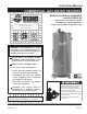
Instruction Manual commercial gas water heaters MODELS N71120NE thru N85390NE/A Low NOx SERIES 108 www.reliancewaterheaters.com 500 Tennessee Waltz Parkway, Ashland City, TN 37015 INSTALLATION - OPERATION - SERVICE - MAINTENANCE - LIMITED WARRANTY Complies with SCAQMD Low NOx Rule 1146.
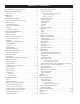
Table Of Contents Safe Installation, Use and Service ����������������������������������������� 3 Water Heater Installation ��������������������������������������������������� 20-23 General Safety Information ��������������������������������������������������� 4-5 Water Line Connections ������������������������������������������������������������������ 20 Precautions ���������������������������������������������������������������������������������������� 4 Water (Potable) Heating and Space Heating �����
Safe Installation, Use and Service The proper installation, use and servicing of this water heater is extremely important to your safety and the safety of others. Many safety-related messages and instructions have been provided in this manual and on your own water heater to warn you and others of a potential injury hazard. Read and obey all safety messages and instructions throughout this manual.
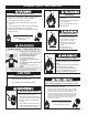
General Safety Information Fire or Explosion Hazard Fire Hazard Do not store or use gasoline or other flammable vapors and liquids in the vicinity of this or any other appliance. For continued protection against risk of fire: Avoid all ignition sources if you smell gas. Do not expose water heater controls to excessive gas pressure. Do not install water heater on carpeted floor. Do not operate water heater if flood damaged. Use only the gas shown on the water heater rating label.
General Safety Information Read and understand this instruction manual and the safety messages herein before installing, operating or servicing this water heater. Explosion Hazard Overheated water can cause water tank explosion. Failure to follow these instructions and safety messages could result in death or serious injury. Properly sized temperature and pressure relief valve must be installed in the opening provided. This manual must remain with the water heater.
Introduction Thank You for purchasing this water heater. Properly installed and maintained, it should give you years of trouble free service. below) in the field involved. Installation skills such as plumbing, air supply, venting, gas supply and electrical supply are required in addition to electrical testing skills when performing service. Abbreviations Used ANSI Z223.1 2006 Sec. 3.3.
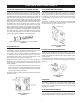
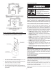
FEATURES AND COMPONENTS the Hydro Cannon (self-cleaning system) electronic ignition control These units include The Hydro Cannon (Self-Cleaning System) installed in the front water inlet, See Figure 1. The Hydro Cannon inlet tube can only be used in the front water inlet connection. Do not install the Hydro Cannon inlet tube in either the top or back inlet water connection. The Hydro Cannon must be oriented correctly for proper function.
installation considerations Rough In Dimensions TOP OUTLET 1 1/2” NPT TOP INLET 1 1/2” NPT F TOP VIEW FIGURE 5. FRONT VIEW BACK VIEW TABLE 1. ROUGH-IN-DIMENSIONS N71 120NE Model Dim. inches mm A 63 1800 B 4 1/4 108 59 1/2 1511 C D 50 7/8 1292 E 19 11/16 500 F 19 483 G 3/4 NPT H 51 7/8 1318 I 5 127 J 27 3/4 705 K 1 1/2 NPT L 1 1/2 NPT Approx. Shipping 520 Ibs. 236 Kg. Weight STD Approx.
Installation Considerations locating the water heater THE HEATER MUST NOT BE LOCATED IN AN AREA WHERE IT WILL BE SUBJECT TO FREEZING. CAUTION LOCATE IT NEAR A FLOOR DRAIN. THE HEATER SHOULD BE LOCATED IN AN AREA WHERE LEAKAGE FROM HEATER OR CONNECTIONS WILL NOT RESULT IN DAMAGE TO ADJACENT AREA OR TO LOWER FLOORS OF THE STRUCTURE. Property Damage Hazard • All water heaters eventually leak. WHEN SUCH LOCATIONS CANNOT BE AVOIDED, A SUITABLE DRAIN PAN SHOULD BE INSTALLED UNDER HEATER.
INSULATION BLANKET Breathing Hazard - Carbon Monoxide Gas Do not obstruct water heater air intake with insulating blanket. Gas and carbon monoxide detectors are available. Install water heater in accordance with the instruction manual. Breathing carbon monoxide can cause brain damage or death. Always read and understand instruction manual. Insulation blankets are available to the general public for external use on gas water heaters but are not necessary with these products.
TION Some circulating pumps are manufactured with sealed bearings and do not require further lubrication. Some circulating pumps must be periodically oiled. Refer to the pump manufacturer’s instructions for lubrication requirements. Breathing Hazard - Carbon Monoxide Gas CIRCULATING PUMP WIRING DIAGRAM Under noTOGGLE circumstances should DISHWASHER LOOP WITH SWITCH the input exceed the rate shown DISHWASHER FIELD SUPPLIED TEMPERATURE on the water heater’s rating label.
Installation Requirements WATER TEMPERATURE CONTROL AND Mixing Valves Gas pressure requirements All models require a minimum gas supply pressure of 5.2” W.C. The minimum supply pressure is measured while gas is not flowing (static pressure) AND while gas is flowing (dynamic pressure). The supply pressure (static and dynamic) should never fall below 5.2” W.C. The supply pressure should be measured with all gas fired appliances connected to the common main firing at full capacity.
Dishwashing Machines A properly sized thermal expansion tank must be installed on all closed systems to control the harmful effects of thermal expansion. Contact a local plumbing service agency to have a thermal expansion tank installed. All dishwashing machines meeting the National Sanitation Foundation requirements are designed to operate with water flow pressures between 15 and 25 pounds per square inch (103 kPa and 173 kPa).
No valve or other obstruction is to be placed between the Temperature-Pressure Relief Valve and the tank. Do not connect discharge piping directly to the drain unless a 6” (15.2 cm) air gap is provided. To prevent bodily injury, hazard to life, or property damage, the relief valve must be allowed to discharge water in adequate quantities should circumstances demand. If the discharge pipe is not connected to a drain or other suitable means, the water flow may cause property damage.
Never obstruct the flow of ventilation air. If you have any doubts or questions at all, call your gas supplier. Failure to provide the proper amount of combustion air can result in a fire or explosion and cause property damage, serious bodily injury or death. Openings must be installed to provide fresh air for combustion, ventilation and dilution in confined spaces.
Multiple heater manifold Outdoor Air Through One Opening Figure 13 and tables on pages 17 and 18 should be used for horizontally manifolding two or more heaters. Figure 15. Alternatively a single permanent opening, commencing within 12 inches (300 mm) of the top of the enclosure, shall be provided. See Figure 14. The water heater shall have clearances of at least 1 inch (25 mm) from the sides and back and 6 inches (l50 mm) from the front of the appliance.
Outdoor Air Through Two Vertical Ducts When ducts are used, they shall be of the same cross sectional area as the free area of the openings to which they connect. The minimum dimension of rectangular air ducts shall be not less than 3 inches. The illustrations shown in this section of the manual are a reference for the openings that provide fresh air into confined spaces only. Air From Other Indoor Spaces Do not refer to these illustrations for the purpose of vent installation.
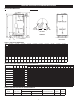
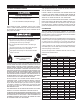
TABLE 7. TECHNICAL DATA VENTING TYPE B GAS VENT Multiple Gas Fired Tank-Type Heaters When venting multiple tank type heaters using Type B vent pipe, follow the installation diagram (figure 13) and tables below which give sizing and data based upon NFPA 54/ANSI Z223. 1992. MODEL N71120NE Input: 120,000 Btu/hr Total Vent Height (Feet) Vent Connector Size: 5 inches Number of Heaters 2 3 4 MODEL N81154NE Input: 154,000 Btu/hr Vent Connector Size: 6 inches Input Btu/hr 120,000 Rise 1 Ft.
TABLE 8.
water heater installation Water Line Connections T&P Valve Discharge Pipe This manual provides detailed installation diagrams (see pages 34-48 of this manual) for typical methods of application for the water heater(s). Explosion Hazard The water heater may be installed by itself, or with a separate storage tank, on both single and two-temperature systems. When used with a separate storage tank, the circulation may be either by gravity or by means of a circulating pump.
Installation diagrams - top inlet/outlet usage code restrictions The type, size and location of the relief valves must be in accordance with local codes. The locations of the relief valves shown in the installation diagrams are typical. See pages 34-48. The heater has a factory installed high temperature limit switch and temperature and pressure relief valve.
heater wiring All electrical work must be installed in accordance with the latest version of the National Electrical Code ANSI/NFPA No. 70 and must conform to all local code authority having jurisdiction. AN ELECTRICAL GROUND IS REQUIRED TO REDUCE RISK OF ELECTRICAL SHOCK OR POSSIBLE ELECTROCUTION. If any of the original wire as supplied with the appliance must be replaced, use only type 105°C thermoplastic or equivalent 2500C type F must be used for the flame sensor and igniter leads.
GAS PIPING NEED NOT BE DISCONNECTED, BUT MUST BE ISOLATED FROM THE SUPPLY PRESSURE TEST BY CLOSING THE MANUAL GAS SHUTOFF VALVE. Contact your local gas service company to ensure that adequate gas service is available and to review applicable installation codes for your area. GAS PIPING AND DIRT LEG INSTALLATION Size the main gas line in accordance with Table 9. The figures shown are for straight lengths of pipe at 0.5 in. W.C. pressure drop, which is considered normal for low pressure systems.
OPERATION IMPORTANT THE GAS VALVE MUST HAVE BEEN IN THE OFF POSITION FOR AT LEAST 5 MINUTES. This waiting period is an important safety step. Its purpose is to permit gas that may have accumulated in the combustion chamber to clear. IF YOU DETECT GAS ODOR AT THE END OF THIS PERIOD DO NOT PROCEED WITH LIGHTING. RECOGNIZE THAT GAS EVEN IF IT SEEMS WEAK, MAY INDICATE PRESENCE OF ACCUMULATED GAS SOMEPLACE IN THE AREA WITH RISK OF FIRE OR EXPLOSION. SEE THE FRONT PAGE FOR STEPS TO BE TAKEN.
LIGHTING & OPERATION LABEL FIGURE 22.
CHECKING VENTING The following steps shall be followed with each appliance connected to the venting system placed in operation, while any other appliances connected to the venting system are not in operation. 1. Seal any unused openings in the venting system. FIGURE 23. IGNITER 2. Inspect the venting system for proper size and horizontal pitch, as required in the National Fuel Gas Code, ANSI Z223.1or the CAN/CGA B149 Installation Codes and these instructions.
CHECKING THE INPUT (3600/15.1) x 1050 = 250,000 (Compare with N100 250NE model and rating.) For appliance installation locations with elevations above 2000 feet, refer to HIGH ALTITUDE INSTALLATIONS section of this manual for input reduction procedure. Should it be necessary to adjust the gas pressure to the burners to obtain the full input rate, the steps below should be followed: 1.
mAINTENANCE venting system Examine the venting system every six months for obstructions and/or deterioration of the vent piping. Remove all soot or other obstructions from chimney which will retard free draft. remote storage tank temperature control The water temperature in the remote storage tank (if used) is controlled by the storage tank temperature control. The sensing element is mounted in the hot water storage tank, see Water Piping Diagram section. FIGURE 26.
anode rod inspection the water is no longer hot. Then close the hot water faucet. Connect a hose to the drain valve and terminate it to an adequate drain. 5. Ensure the drain hose is secured before and during the entire flushing procedure. Flushing is performed with system water pressure applied to the water heater. 6. Open the water heater drain valve to flush the storage tank. 7. Flush the water heater storage tank to remove sediment and allow the water to flow until it runs clean. 8.
deliming solvents A. O. Smith recommends the use of UN•LIME for deliming. UN•LIME is a patented food grade acid which is safe to handle and does not create the harmful fumes which are associated with other products. Explosion Hazard Flammable hydrogen gases may be present. UN•LIME may be obtained from your dealer, distributor or A. O. Smith Product Service Division. Order Part Number 9005416105, 1 gallon, packed 4 gallons per case or Part Number 9005417105, 5 gallon container.
8. Remove the cleanout cover and place a clean plastic bucket next to the cleanout opening. Note: To check UN•LIME for continued use, place some scale or white chalk in a glass with a small amount of UN•LIME. If the material is vigorously dissolved by the UN•LIME, it can be reused; if not, the UN•LIME should be replaced. Partially open the cold water inlet valve to allow time to accomplish the following and then close the valve.
SERVICE ELECTRICAL SERVICING The installer may be able to observe and correct certain problems which may arise when the unit is put into operation. HOWEVER, it is recommended that only qualified service agents, using appropriate test equipment, be allowed to service the heater. As preliminary step, check wiring against diagram, check for grounded, broken or loose wires. Check all wire ends to be sure that they are making good contact. LABEL ALL WIRES PRIOR TO DISCONNECTION WHEN SERVICING CONTROLS.
SEQUENCE OF OPERATION FLOW CHART Description of this flow chart can be found in the “SEQUENCE OF OPERATION” section found on page 23.
operational checklist COMPLAINT *Water not hot enough CAUSE USER REMEDY SERVICE AGENT Thermostat set too low. Set thermostat dial to a higher temperature Upper and/or lower temperature probe out of calibration. Call service agent *Insufficient hot water Thermostat set too low. *See WATER TEMPERATURE CONTROL WARNING (on page 11). Set thermostat dial to a higher temperature Upper and/or lower temperature probe out of calibration.
ALT. COLD WATER CONNECTION HOT WATER TO FIXTURES NOTES: 1. Preferred piping diagram. 2. The temperature and pressure relief valve setting shall not exceed pressure rating of any component in the system. 3. Service valves are shown for servicing unit. However, local codes shall govern their usage. 4. The Tank Temperature Control should be wired to and control the pump between the water heater(s) and the storage tank(s). 5.
HOT WATER TO FIXTURES ALTERNATE LOCATION NOTES: 1. Preferred piping diagram. 2. The temperature and pressure relief valve setting shall not exceed pressure rating of any component in the system. 3. Service valves are shown for servicing unit. However, local codes shall govern their usage. 4. The Tank Temperature Control should be wired to and control the pump between the water heater(s) and the storage tank(s). 5.
HOT WATER RETURN TEMPERED WATER OUTLET COLD HOT HOT WATER OUTLET NOTES: 1. Preferred piping diagram. 2. The temperature and pressure relief valve setting shall not exceed pressure rating of any component in the system. 3. Service valves are shown for servicing unit. However, local codes shall govern their usage. 4. The Tank Temperature Control should be wired to and control the pump between the water heater(s) and the storage tank(s).
PIPE T&P TO OPEN DRAIN NOTES: 1. Preferred piping diagram. 2. The temperature and pressure relief valve setting shall not exceed pressure rating of any component in the system. 3. Service valves are shown for servicing unit. However, local codes shall govern their usage. 4. The Tank Temperature Control should be wired to and control the pump between the water heater(s) and the storage tank(s).
PIPE T&P TO OPEN DRAIN NOTES: 1. Preferred piping diagram. 2. The temperature and pressure relief valve setting shall not exceed pressure rating of any component in the system. 3. Service valves are shown for servicing unit. However, local codes shall govern their usage. 4. The Tank Temperature Control should be wired to and control the pump between the water heater(s) and the storage tank(s). 5. The water heater’s operating thermostat should be set 5 degrees F higher than the Tank Temperature Control.
PIPE T&P TO OPEN DRAIN NOTES: 1. Preferred piping diagram. 2. The temperature and pressure relief valve setting shall not exceed pressure rating of any component in the system. 3. Service valves are shown for servicing unit. However, local codes shall govern their usage. 4. The Tank Temperature Control should be wired to and control the pump between the water heater(s) and the storage tank(s). 5. The water heater’s operating thermostat should be set 5 degrees F higher than the Tank Temperature Control.
PIPE T&P TO OPEN DRAIN HOT WATER TO FIXTURES DRAIN EXPANSION TANK COLD WATER SUPPLY TANK TEMPERATURE CONTROL CIRCULATING PUMP PRESSURE RELIEF VALVE TEMPERATURE & PRESSURE RELIEF VALVE ALTERNATE LOCATION NOTES: 1. Preferred piping diagram. 2. The temperature and pressure relief valve setting shall not exceed pressure rating of any component in the system. 3. Service valves are shown for servicing unit. However, local codes shall govern their usage. 4.
EXPANSION TANK COLD WATER SUPPLY HOT WATER RETURN HOT WATER TO FIXTURES PRE-HEATED WATER TO BOOSTER DRAIN BOOSTER HEATER WATER FLOW SWITCH TEMPERATURE GAGE CHECK VALVE FULL PORT BALL VALVE BOOSTER WATER RETURN TANK TEMPERATURE CONTROL CIRCULATING PUMP PRESSURE RELIEF VALVE TEMPERATURE & PRESSURE RELIEF VALVE BOOSTER WATER TO FIXTURES NOTES: 1. Preferred piping diagram. 2. The temperature and pressure relief valve setting shall not exceed pressure rating of any component in the system. 3.
PRE-HEATER PRE-HEATER MUST BE IDENTICAL HEATERS PIPE T&P TO OPEN DRAIN DRAIN BOOSTER RETURN (IF USED) EXPANSION TANK COLD WATER SUPPLY TANK TEMPERATURE CONTROL CIRCULATING PUMP PRESSURE RELIEF VALVE TEMPERATURE & PRESSURE RELIEF VALVE HOT OUTLET AT STORED TEMPERATURE BOOSTED WATER OUTLET TYPICAL BOOSTER HEATER PIPE T&P TO OPEN DRAIN NOTES: 1. Preferred piping diagram. 2. The temperature and pressure relief valve setting shall not exceed pressure rating of any component in the system. 3.
PIPE T&P TO OPEN DRAIN PIPE T&P TO OPEN DRAIN NOTES: 1. Preferred piping diagram. 2. The temperature and pressure relief valve setting shall not exceed pressure rating of any component in the system. 3. Service valves are shown for servicing unit. However, local codes shall govern their usage. PIPE T&P TO OPEN DRAIN HOT WATER TO FIXTURES WARNING: THIS DRAWING SHOWS SUGGESTED PIPING CONFIGURATION AND OTHER DEVICES; CHECK WITH LOCAL CODES AND ORDINANCES FOR ADDITIONAL REQUIREMENTS.
PIPE T&P TO OPEN DRAIN HEATER PIPE T&P TO OPEN DRAIN HEATER PIPE T&P TO OPEN DRAIN DRAIN TANK TEMPERATURE CONTROL CIRCULATING PUMP PRESSURE RELIEF VALVE ALT. COLD WATER CONNECTION EXPANSION TANK HOT WATER RETURN WATER FLOW SWITCH TEMPERATURE GAGE CHECK VALVE FULL PORT BALL VALVE COLD WATER SUPPLY LEGEND TEMPERATURE & PRESSURE RELIEF VALVE HOT WATER TO FIXTURES NOTES: 1. Preferred piping diagram. 2.
HEATER PIPE T&P TO OPEN DRAIN HEATER PIPE T&P TO OPEN DRAIN HEATER AOS STORAGE TANK HOT WATER TO FIXTURES NOTES: 1. Preferred piping diagram. 2. The temperature and pressure relief valve setting shall not exceed pressure rating of any component in the system. 3. Service valves are shown for servicing unit. However, local codes shall govern their usage. 4. The Tank Temperature Control should be wired to and control the pump between the water heater(s) and the storage tank(s). 5.
PIPE T&P TO OPEN DRAIN PIPE T&P TO OPEN DRAIN PIPE T&P TO OPEN DRAIN NOTES: 1. Preferred piping diagram. 2. The temperature and pressure relief valve setting shall not exceed pressure rating of any component in the system. 3. Service valves are shown for servicing unit. However, local codes shall govern their usage. FINISHED FLOOR HOT WATER TO FIXTURES WARNING: THIS DRAWING SHOWS SUGGESTED PIPING CONFIGURATION AND OTHER DEVICES; CHECK WITH LOCAL CODES AND ORDINANCES FOR ADDITIONAL REQUIREMENTS.
HEATER HEATER PIPE T&P TO OPEN DRAIN HEATER PIPE T&P TO OPEN DRAIN PIPE T&P TO OPEN DRAIN NOTES: 1. Preferred piping diagram. 2. The temperature and pressure relief valve setting shall not exceed pressure rating of any component in the system. 3. Service valves are shown for servicing unit. However, local codes shall govern their usage. 4. The Tank Temperature Control should be wired to and control the pump between the water heater(s) and the storage tank(s). 5.
HEATER HEATER PIPE T&P TO OPEN DRAIN HEATER PIPE T&P TO OPEN DRAIN DRAIN AOS STORAGE TANK ALTERNATE LOCATION PIPE T&P TO OPEN DRAIN TANK TEMPERATURE CONTROL CIRCULATING PUMP PRESSURE RELIEF VALVE TEMPERATURE & PRESSURE RELIEF VALVE HOT WATER TO FIXTURES NOTES: 1. Preferred piping diagram. 2. The temperature and pressure relief valve setting shall not exceed pressure rating of any component in the system. 3. Service valves are shown for servicing unit.
MANIFOLD KITS TWO UNIT MANIFOLD KIT (PART NO. 9003426205) MODEL N71 120NE N81 154NE N100 180NE N100 199NE N100 200NES N100 250NE N100 275NE N85 310NE N85 366NE N85 390NE THREE UNIT MANIFOLD KIT (PART NO. 9003427205) DIMENSION "A" 63" 68" 72" 72" 72" 72" 72" 73" 73" 73" FOUR UNIT MANIFOLD KIT (PART NO.
notes 51
notes 52
notes 53
notes 54
Limited Warranty Reliance Water Heater Company, the warrantor, extends the following LIMITED WARRANTY to the owner of this water heater. 1. THE TANK If the glass-lined tank in this water heater shall prove upon examination by the warrantor to have leaked due to natural corrosion from potable water THREE years after initial installation, the warrantor will supply a complete new Reliance water heater of equivalent size and therein, during the current model.
www.reliancewaterheaters.com 500 Tennessee Waltz Parkway, Ashland City, TN 37015 Tech Support: 800-365-4054 Parts: 800-821-2017 Copyright © 2010 Reliance Water Heater Company, All rights reserved.