Remeha Gas 360 S English Gas-fired boilers 20/07/05 Technical instructions
Contents Introduction . . . . . . . . . . . . . . . . . . . . . . . . . . . . . . . . . . . . . . . . . . . . . . . . . . . . . . . . . . . . . . . . . . . . . . . . . . . . . . . . .3 1 Regulations . . . . . . . . . . . . . . . . . . . . . . . . . . . . . . . . . . . . . . . . . . . . . . . . . . . . . . . . . . . . . . . . . . . . . . . . . . . . . . . . . . . . . . . . . . . . . .3 2 Symbols used. . . . . . . . . . . . . . . . . . . . . . . . . . . . . . . . . . . . . . . . . . . . . . . . . . . . . . .
Introduction This product will be marketed in the following European Union member states: GB - HU - ES Directive 97/23/CE The boilers and hot water tanks are designed and manufactured in accordance with the sound engineering practice, as requested in article 3.3 of the directive 97/23/EC; it is certified by compliance with the directives 90/396/EC, 92/42/EC, 73/23 EC and 89/336/EC.
Description 1 Introduction Gas 360 S boilers are made of cast iron: - with atmospheric gas burners - with electronic ignition via the ignition burner for hot water central heating - with a useful output of between 54 and 117 kW The figure given after Gas 360 S indicates the number of sections which make up the boiler. Gas 360 S boilers are delivered with a K control panel. They can be fitted with an optional RC4 and RC5 control unit (master-slave control unit options).
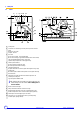
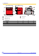
3 Main parts 3.1 Boiler 2 7 8 9 10 11 1 6 3a 3b 4b 8502N169A 4a 5a 5b 1 Control panel 2 Connection for a minimum gas control pressure pressure-sensitive switch Natural gas: 12.5 mbar Propane: 20 mbar 3 Gas valve: a. Gas valve 1st stage ; Type VK4100C1026 b. Gas valve 2nd stage ; Type VK4105C1066 (Formats: 8-12 sections) and Type VR4605CB1033 (Formats: 14 sections) Ignition of the principal burner is done progressively. 4 Flame inspection window a. Flame inspection window 1st stage b.
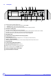
3.2 Control panel 1 3-position switch Auto / Manual ! / TEST STB - The switch may be left on either position manual ! or automatic AUTO. - STB TEST: temporary action to test the safety thermostat. - Press the TEST STB switch and set pump shut-off switch (2) 9 to the “Summer” position %. 2 Switch Burner / Heating pump: This button is used to control the burner and the heating pump. Both buttons are in “Winter” .
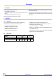
4 Technical characteristics The boilers can operate on natural gas H/E or propane. Conversion to propane is done following the operations described in the chapter "Adaptation to another gas". Boiler Gas 360 S/ Useful efficiency Power input Flue gas temperature Tf 12 14 kW 36 45 54 54 2nd stage kW 63 81 99 117 1st stage kW 39.4 49.1 58.8 58.8 2nd stage kW 68.9 88.4 107.8 127.
5 Identification plate The rating plate affixed to the front panel during assembly provides the exact identification of the boiler and indicates its principal characteristics.
6 Main dimensions Connection for safety valves Rp 1 Draining Rp 3/4 Heating outlet R 1 1/2 Gas inlet R 1 Heating return R 1 1/2 9 Boiler Gas 360 S 8 10 12 14 A (mm) 946 1113 1280 1447 B (mm) 952 1007 1007 1007 C (mm) 102 124 124 124 E (mm) 75 75 75 75 F (mm) 494 578 661 745 Ø G interior (mm) 180 200 200 225 Remeha Gas 360 S 20/07/05 - 300005180-001-A
Operation 1 Furnace operation equipped with safety box S4565 BF 1161 Operating principle The ignition and burner surveillance sequences are ensured by the safety box. Behaviour in normal conditions If needed, the boiler thermostat TCH1 closes the contact. The ignition transformer TA integrated into the safety control box and the ignition burner valve VBA (supply to the ignition burner) are switched on.
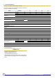
Normal operating cycle Operating cycle on safety (start up without flame signal) A B C CO D SF TA TCH1 TCH2 VA VBa VP1 VP2 t3n tr ts tva tw tc 11 Heat requirement 1 and 2 stage Formation of flame in ignition burner Heat requirement 1 Speed Closing valve On safety through absence of flame signal Burner flame signal Ignition transformer Boiler thermostat 1 Speed Boiler thermostat 2 Speed Safety lockout warning light Ignition burner valve Main burner valve 1 Speed Main burner valve 2 Speed Flame stabilisat
1.
1.
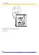
Adapting to another gas Valid for switching from natural gas H/E to propane and vice versa. 1 Changing the burner nozzles - Remove the nozzles with a 12 mm spanner and fit the new nozzles with their new seals. First tighten the nozzles by hand and carefully lock them using a spanner. Carry out a leak tightness check. 2 Changing the ignition burner injector Unscrew the connecting nut (14 spanner), Fit the new nozzle . Pull the gas supply pipe towards yourself.
3 Setting the nozzle pressure Pressure socket The pressure must be set by a qualified professional. The boiler must be commissioned after having checked the points covered in this chapter: Final checks before commissioning. - Connect the manometer to the left or right pressure outlet on the manifold. - Turn the boiler on. Set the boiler thermostats to maximum. - Unscrew the protection cap on each valve.
4 Setting the start up pressure 1/4 turn Natural gas Propane or If necessary, the start-up pressure can be set on the right valve (1st stage) using a flat screwdriver. To modify this setting, it necessary first to remove the protection using a screwdriver (1/4 turn). In the factory, it is set to maximum..
4.1 Operation of the progressivity screw setting 8502N211 A. Downstream pressure (mbar) B. Time (s) 5 Attaching the label Affix the label which indicates for which type of gas the boiler is fitted and set.
Commissionning 1 Pressure settings and calibrated nozzle markings 1.1 Table of pressure settings and nozzle markings Boiler type Gas 360 S/ 8 10 12 14 Nozzle pressure Natural gas H mbar 14 14 14 14 Propane mbar 36 36 36 36 Natural gas H mbar 11 11 11 11 Propane mbar 10 10 10 10 7 9 11 13 Nozzle markings natural gas H/E 257B 257B 257B 257B Marking, propane nozzles 160B 160B 160B 160B 8 10 12 14 m3/h 7.29 9.35 11.41 13.46 kg/h 5.35 6.87 8.37 9.
2 Final checks before commissioning first start-up is to be performed by your installation The engineer. Check the following points before starting the heater: Hydraulic circuit: `Check that the installation and boiler are adequately filled with water and correctly irrigated and bled. `Check that the hydraulic connections are leak tight. Gas circuit: `Check the adjustment of the gas line: - Connect a manometer to the pressure socket located on the manifold.
Maintenance 1 Checking and cleaning the main components 1.1 Cleaning heater body The extent of clogging on the heating body must be checked once a year. If it is necessary to sweep the boiler, remove the burner drawer to prevent deposits and soot blocking the orifices in the gas trains.
1.2 Cleaning main burner and ignition burner The main burner and the ignition burner injector with its filter must be regularly cleaned to ensure good performance. We recommend doing this at least once a year.
Incidents and solutions Symptoms Probable causes Solution The heater does not start - The heater thermostat is and the safety box is not requiring heat - Create a demand by moving the heater thermostat or the setting level affected (red alarm - Setting (option) is not requiring (option). indicator off) heat. - The safety thermostat has been - Solve the cause of overheating and reset the safety thermostat. triggered after overheating.
Symptoms Noisy heater Probable causes Solution - Poor purge - Purge correctly - Body has scale - Descale the heating circuit - Unsuitable injectors (Whistling) - Check injectors Heater too hot or too cold - 3 position switch on position ! - Check the position of the 3 position switch for requirements - Wrong setting for the heater - Set the heater thermostat if the heater has SV-matic setting or an ambient thermostat thermostat Flame returns - Injectors too large - Pressure too weak - Check pres
Spare parts Gas 360 S The code number on the list next to the required piece must be stated when ordering replacement parts.
Gas line 8-10-12 sections 25 Remeha Gas 360 S 20/07/05 - 300005180-001-A
Gas line 14 sections 26 Remeha Gas 360 S 20/07/05 - 300005180-001-A
Control panel K Control panel K + Components 20/07/05 - 300005180-001-A Remeha Gas 360 S 27
Metal casing for control panel K 28 Remeha Gas 360 S 20/07/05 - 300005180-001-A
Boiler body insulation 20/07/05 - 300005180-001-A Remeha Gas 360 S 29
Cladding 30 Remeha Gas 360 S 20/07/05 - 300005180-001-A
Markers Code no. Description Markers Code no.
Markers Code no.
Markers Code no.
Remeha Gas 360 S 20/07/05 - 300005180-001-A
Remeha Gas 360 S 20/07/05 - 300005180-001-A
NL Remeha B.V. Postbus 32 7300 AA APELDOORN Tel: +31 55 5496969 Fax: +31 55 5496496 Internet: nl.remeha.com E-mail: remeha@remeha.com GB Broag Ltd. Remeha House Molly Millars Lane RG41 2QP WOKINGHAM, Berks. Tel: +44 118 9783434 Fax: +44 118 9786977 Internet: uk.remeha.com E-mail: boilers@broag-remeha.com B J.L. Mampaey BVBA Uitbreidingstraat 54 2600 ANTWERPEN Tel: +32 3 2307106 Fax: +32 3 2301153 Internet: www.mampaey.be E-mail: info@mampaey.be B Thema S.A.