
On-Chip Flash Microcontroller User Manual


5. BOARD OPTIONS
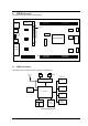
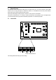
The EDK has a number of configuration settings set by four jumpers CJ4 (A, B, C, D) and zero-ohm links. Common EDK
functions can be set using the jumpers as described in sections 5.2. The additional zero-ohm links provide additional
features that may be required to interface with other systems.
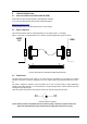
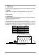
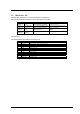
All the Jumper link settings are three pin options. There are four sets of options on each header.
The headers are numbered from 1 to 12 with pin 1 marked on the PCB by an arrow pointing to the pin. The diagram below
shows the numbering of these jumper links and indicates jumpers fitted 1-2 for each three-pin jumper.
5.1. JUMPER LINKS
Jumper
A
1,2,3
Jumper
B
1,2,3
Jumper
C
1,2,3
Jumper
D
1,2,3
13213221 3123
12 4 1210863 57911
9-Way
D-Type
Power
RESET
Switch
NMI
Switch
User1 LED
User2 LED
Power LED
FLASH
Programming
CJ4
5V
UVcc
GND
RESn
FW
NMIn
ULED1
ULED2
PSCK
PTXD
PRXD
RX232
TX232
CTS
RTS
Microprocessor
LIN
I2C
J1
J2
XTAL
OSC
Testpoints
SPI
DEBUG
LINI2C
FIGURE 5-1: JUMPER CONFIGURATION
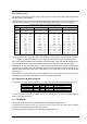
The following tables define each jumper and its settings.
9