Operating instructions 2-channel code lock Item No.
Table of contents Page 1. Introduction...........................................................................................................................4 2. Explanation of symbols........................................................................................................4 3. Intended use.........................................................................................................................5 4. Delivery content........................................................
Page o) Status tones................................................................................................................35 p) LED indicators.............................................................................................................36 q) Door open delay..........................................................................................................36 r) Open door warning.................................................................................................
1. Introduction Dear customer, Thank you for purchasing this product. For safety reasons, always follow the instructions in this manual. These operating instructions contain important information on setting up and using the product. Please consider this if you give the product to a third party, and keep the instructions for future reference. If there are any technical questions, please contact: International: www.conrad.com/contact United Kingdom: www.conrad-electronic.co.uk/contact 2.
3. Intended use This standalone digital code lock is designed for private and commercial use. It is primarily intended for for independent 12 V locking systems. The code lock is compatible with most electrical lock systems. It can also be integrated into existing security systems and machines. The code lock has three types of output for different security technologies/peripherals. It is only designed for indoor use.
5. Safety instructions Read the operating instructions and safety information carefully. We shall not be liable for damage to property or personal injury caused by incorrect handling or failure to follow these instructions and observe the safety information! Such cases will void the warranty. • The code lock must not be modified or converted, as this will void the warranty and the product certification. • This product is not a toy. Keep it out of the reach of children and pets.
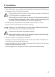
6. Installation • Check whether there are any cables or wires underneath the mounting surface. These may be damaged when you drill holes into the surface. Disconnect the wires from the mains and ensure that they cannot be switched back on. Check that there is no voltage on the wires. Take care not to short circuit the input and output wires. Keep the wires separate from one another.
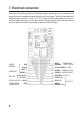
7. Electrical connection Connect the 16 cables according to the following diagram. Alternatively, you can release the pin strip and connect a separate connector directly to the circuit board. The circuit board features 6 additional screw contacts (T1: open, T2-4, T5-7). Insert the ends of the cables into these contacts and tighten the screws. You can also use the 3 jumper contacts. Ensure that the soldering joints are reliable and strip all open cable contacts to a sufficient length.
T2-T3: Output 1 – Door lock: Connect the door lock directly to these inputs. Ensure that terminals 2 (-) and 3 (+) are connected in the correct polarity. This connection delivers a maximum current of 3 A at 12 V/DC. By default, this output is “Fail-Secure” (the output locks the door when power is removed). It can be changed to “Fail-Safe” using program code 66. In this scenario, output 1 opens the door when there is no power supply. Use program codes 40–43 to configure the output settings.
1-2: Tamper monitor: The contact between pin 1 and pin 2 is broken if the code lock is opened. The contacts can be integrated into a 24-hour surveillance system for comprehensive monitoring. The connections can be left unconnected.
13: Inhibiting input: When this input is set to GND(-), it cannot be enabled by the door opener or by entering a code from user group 1. This input is designed for use with several code locks that control one door lock. It can be connected to output 14. This is an NPN open collector output. 14: Communication: This output is normally open and is switched to GND(-) for 5 seconds when the door lock is opened with a code from user group 1 or a door opener.
8. LED indicators The code lock features 4 LED indicators. One of the LEDs functions as a status indicator. Two of the LEDs can be manually configured, and the other LED indicates an incorrect code entry for user group 1; it can also be manually configured using a jumper. Note that the MAIN/Auxiliary LED is a dual LED (in the same unit). Main LED (green): This LED functions as the status indicator. It flashes when the combination lock is in standby and indicates when a button is pressed.
9. Status tones and LED prompts By default, the internal buzzer and the MAIN LED indicator produce the following signals: Status Audio signal* LED indicator 1 Program mode --- Constant 2 Correct key 1 audio tone 1 flash 3 Correct code 2 audio tones 2 flashes 4 Incorrect code 5 audio tones 5 flashes 5 DAP jumpers are not set Continuous audio tone Constant 6 Standby mode --- Flashes (0.
10. Overview The default master code is 0000. For security reasons, change the master code when you configure the code lock. A) Accessing programming mode with the master code Enter master code Confirm Remarks: xxxx * Enable program mode B) System reset – for installation technicians Reset code Confirm Remarks: 8901 # The system will be reset. All saved data will be deleted (except the master code).
2) Super user code Program code Code input Confirm Remarks 45 4–8 digits # Owner's multitask code 3) Emergency code Program code User ID Code input Confirm Remarks 46 0 to 9 4–8 digits # 10 emergency codes for enabling the emergency output / output 1 and notifying that the user is in distress.
D) Configuring the output modes Program code Duration Confirm Remarks 40 1 to 999 # Output 1, keep current mode for 1–999 seconds. 41 # Output 1, start/stop (toggle) 42 # Output 1, start/stop (toggle) with 2-digit start code 43 # Output 1, start/stop (toggle) with 3-digit start code # Output 2, keep current mode for 1–999 seconds.
F) Incorrect code input and reporting Program code Lock mode Confirm Remarks 70 1 # 10 consecutive incorrect entries: The keypad is locked for 30 seconds. 70 2 # 10 consecutive incorrect entries: The emergency output is activated. 70 5 to 10 # The keypad is locked for 15 minutes after 5–10 incorrect code attempts. You can unlock the keypad at any time with the super user code. 70 0 # All security settings are disabled.
I) Confirmation of user codes Program code Function code Confirm Remarks 82 0 # Manually confirm user codes with the # key. The master code does not need to be the same length as the user codes. The codes can be 4–8 digits long. 82 1 # Automatically confirm user codes The user codes must be the same length as the master code. You do not need to press the # key to confirm a code entry.
L) Door open delay Program code Function code Confirm Remarks 85 # 0 - Disabled 0 to 4 1 - Press, 5 second delay with warning 2 - Press, 10 second delay with warning 3 - Press and hold, 5 second delay with warning 4 - Press and hold, 10 second delay with warning M) Open door warning Program code Function code Confirm Remarks 9 0 # No warning 9 1 to 999 # The code lock sounds a warning when the door has been open for 1–999 seconds.
11. Settings and programming Prerequisites • The keypad must be placed in programming mode in order to configure the settings. • A ll settings data is saved to a non-volatile memory. This means that the data is not deleted when the code lock is switched off. • D o not turn off the power supply when you are programming the keypad, as this may corrupt the memory. a) Enabling/disabling programming mode The master code is required to enable programming mode. 1.
DAP jumper (resets the master code) If you have forgotten the master code, follow the steps below to perform a hardware reset: 1. Disconnect the keypad from the power supply: 2. Connect the DAP jumper from OFF to ON using the plug-in contact. 3. Connect the keypad to the power supply. The keypad will start to beep. 4. Connect the DAP jumper from ON to OFF using the plug-in contact. The keypad will stop beeping when the DAP jumper is placed in the output position. 5.
c) Resetting the system Sometimes it may be necessary to delete all data from the memory (apart from the master code) and restore the keypad to the factory settings. For example, this may be necessary if saved data cannot be accessed, or if the code lock has a new owner. Follow the steps below to restore factory settings: 1. Enable programming mode using the master code and the * key. In this example, the master code is 3289: 3 2 8 9 * 2.
For more information about user codes, refer to section C-1 in “Overview”. Refer to the “Overview” section for information about manual and automatic confirmation mode. Programming examples 1. Enter the master code and press the * key to enable programming mode. In this example, the master code is 3289. 3 2 8 9 * 2. Set the user code for output 1 to 8321. In the example, the user ID is 01. 1 0 1 8 3 2 1 # 3. Set the user code for output 2 to 54321. In this example, the user ID is 1.
e) Programming the super user code The super user code is a multitasking code which can be used to enable outputs 1, 2 and 3 at the same time. It can also be used to access the special features of output 1. Program code Super user code Confirm 45 4–8 digits # • The super user code can be 4–8 digits long. In automatic confirmation mode, the super user code must have the same number of digits as the master code. • The super user code and the door opener are independent of all lock systems.
2. Using output 1 to override the door lock Output 1 monitors the door lock. It is possible to keep the door locked, even when a code is entered. This may be useful during holidays. It is also possible to keep the door unlocked. This feature can be configured using the following code: 2 5 8 0 # 7 Door is locked/unlocked • The LED indicator for output 1 (green) turns on when the door is unlocked. • Only use this feature if you are using the door lock in fail-safe mode.
f) Configuring the emergency code The emergency code provides protection for the user in the event that he/she is forced to open the door under duress. It works like a normal user code and enables output 1 to open the door. In addition, the emergency output is automatically enabled. This output reports the incident to a security system or security personnel. • The emergency code can be 4–8 digits long.
Instructions 1. Enter the four-digit user code to enable output 1 and the emergency output. 3 3 5 7 # 2. Enter the five-digit user code to enable output 1 and the emergency output. 2 3 9 8 0 # 3. Enter a normal user code to disable the emergency output (1357 in this example). 1 3 5 7 # The emergency output stays enabled until it is disabled with a user code or the super user code. g) Configuring the visitor code Visitor codes work like user codes.
Programming example 1. Enter the master code and press the * key to enable programming mode. In this example, the master code is 3289. 3 2 8 9 * 2. Set the visitor code to 1378 with ID 0 (single-use code with no time limit). 47 0 0 0 1 3 7 8 # 3. Set the visitor code to 23089 with ID 1 (valid for 5 hours). 47 1 0 5 2 3 0 8 9 # 4. Set the visitor code to 8358 with ID 2 (valid for 10 hours). 47 2 1 0 8 3 5 8 # 5 Press the * key to exit programming mode.
h) Deleting user codes and other function codes You can delete codes for individual users (e.g. when a member of staff leaves the company, or when you want to restrict access rights for a certain individual). Example 1. Enter the master code and press the * key to enable programming mode. In this example, the master code is 3289. 3 2 8 9 * 2. If you wish to disable more than one code, delete the codes one by one.
i) Settings for outputs 1, 2 and 3 Outputs 1,2 and 3 can be enabled/disabled in several ways Program code Duration Confirm 40 1–999 seconds # 41 # 42 # 43 # • The outputs can be activated for 1–999 seconds. • They can be enabled/disabled by entering a user code. • They can be enabled with a short user code and disabled with the full code.
Example: User code: 54321, start code: 543 User code: 927053, start code: 927 Example 1. Enter the master code and press the * key to enable programming mode. In this example, the master code is 3289. 3 2 8 9 * 2. Enable output 1 for 5 seconds 4 0 5 # 3. Enable start/stop mode for output 2 5 1 # 4. Enable start/stop mode for output 3 with a 3-digit start code 6 3 # 5. Press the * key to exit programming mode. Instructions 1.
• If you enable start/stop mode with a 2 or 3-digit start code, the entire code is required to disable the output. This mode can be used to allow personnel to activate a system (e.g. an alarm system) and ensure that it can only be disabled by the owner. • You can also user the super user code to enable/disable the outputs.
k) Multiple incorrect code entries If an incorrect code is entered several times, the keypad can lock the system or inform security personal to prevent unauthorized access. You can configure the following options: Program code Lock options Confirm 70 1–2 digits # Codes for lock options 1 If the wrong code is entered 10 times in a row, the keypad is disabled for 30 seconds (default setting). 2 If the wrong code is entered 10 times in a row, the emergency output is enabled.
l) Door forced open The keypad sets off alarm when the door is forced open without entering a user code or pressing the door opener. The keypad buzzer and the alarm output will be automatically enabled. The alarm output automatically reports the incident to the security system or security personnel. Program code Function Confirm 80 0 or 1 # Options 0 The forced door alarm is switched off (standard setting). 1 The alarm is enabled. The alarm goes off for 60 seconds when the door is forced open.
n) Confirmation mode You can confirm code entries manually with the # key, or you can set the code lock to confirm them automatically. Using manual confirmation mode prevents the user from guessing the length of the user code. Program code Function Confirm 82 0 or 1 # Options 0 M anual confirmation mode (default setting): After entering a user code, press the # key to confirm your entry. In this mode, the user codes can be 4–8 digits long.
p) LED indicators The keypad LED turns on when the keypad is in standby. The LED can be disabled if you do not want it to stay switched on (e.g. if you find it disturbing at night). Program code Function Confirm 84 0 or 1 # Options 0 The LED is switched off in standby mode. 1 The LED turns on when the keypad is in standby. q) Door open delay Access to buildings or rooms can be controlled with user codes. To leave a room or building, press the door release button.
Examples 1. Enter the master code and press the * key to enable programming mode. In this example, the master code is 3289. 3 2 8 9 * 2. Set a 5-second time delay: 8 5 1 # 3. Program output 1 so that the door release button has to be pressed for 5 seconds before the door can be opened. 8 5 3 # 4. Reset the door release button to the default settings. 8 5 0 # 5. Press the * key to exit programming mode.
12. Simplified software version If there is only one user code for each output and you do not require any special features, you can use a simplified software version. No user IDs are required for this software version. The simplified software version is designed for users that prefer an easy setup with the standard settings. Skip this chapter if you do not wish to used the simplified software version. Important Information • You can switch between the full and simplified software versions.
b) Switch to the simplified software version Reset code Confirm Remarks: 8900 # The system will be reset. All saved data will be deleted (except the master code).
Programming examples 1. Enter the master code and press the * key to enable programming mode. The default master code is 0000. Master Code Confirm 0 0 0 0 * The keypad is now in programming mode 2. Reset the system to the simplified software version 8 9 0 0 # 3. Change the master code 0 3 2 8 9 # 4. Set the user code for output 1 to 8321 1 8 3 2 1 # 5. Set the user code for output 2 to 5432 2 5 4 3 2 # 6.
13. Typical applications a) Standard wiring for a single code lock CABLE HARNESS 12 V/DC POWER SUPPLY DOOR OPENER • Connect the flyback diode (1N4004, included with the code lock) to the door lock in series. Place the diode as close as possible to the lock. When an inductance is switched off (electromagnet in the lock), the energy released is routed through the diode. This prevents damage to the code lock.
b) Standard wiring for a single code lock connected to a master system TERMINALS DOOR SENSOR ELECTRIC LOCK SYSTEM DOOR OPENER CABLE HARNESS WHITE/ORANGE YELLOW GREEN PURPLE BLUE WHITE/BROWN YELLOW LIGHT BLUE GREEN GREY BLACK RED EMERGENCY CODE - OUTPUT OUTPUT 2 ENABLES/DISABLES THE ALARM RED LED ALARM STATUS INDICATOR GREEN LED ALARM STATUS INDICATOR TAMPER MONITOR • In this example, the green and red LEDs are connected. These are used to indicate the outputs, alarm, program mode and other features.
c) Standard wiring for two lock systems with two code locks CABLE HARNESS ELECTRIC LOCKING SYSTEM DIODE DOOR SENSOR DOOR 2 SENSOR 12 V/DC POWER SUPPLY DOOR OPENER (OPENS DOOR 1 FROM THE INSIDE) CABLE HARNESS OUTPUT 1 (INHIBITING INPUT) COMMUNICATION COMMON GND NO CONTACT CONNECTION TO OTHER PANEL DOOR LOCKING SYSTEM OUTPUT 1 (INHIBITING INPUT) COMMUNICATION COMMON GND DOOR 1 DOOR 2 NO CONTACT ELECTRIC LOCKING SYSTEM DIODE DOOR SENSOR DOOR 2 SENSOR 12 V/DC POWER SUPPLY CONNECTION TO OTHER
An inter-lock system requires at least two code locks. In this example, two DK-9523 devices are connected. Output 13 is connected to output 14 on the other device. Both devices must be connected to the same GND (-) via output 15. This prevents the second door from opening when the first door is opened. If desired, the green LED can be connected to indicate the door status. • A keypad is placed next to each door on the outside of the room. • A door opener is placed next to each door inside the room.
b) Door sensor When a position sensor (NC - typical magnet sensor) is connected to the door, the code lock can be configured to do the following: • Automatically disable access The sensor contact is broken when the door is opened. The outputs on the door lock are disabled to prevent unauthorized access, even when the preset timer has not elapsed. • Forced door alarm The code lock triggers an alarm when the sensor contact is broken without using the door opener or a correct access code.
c) Keypad entry This NPN transistor (open collector with a maximum current of 100 mA at 24 V/DC) can be used to transfer a signal to other devices when a button is pressed, or when an alarm is triggered after the door is forced open. Keypad-Alarm (K): Output 8 is switched to GND (-) for 10 seconds each time a button is pressed. This can be used to turn on lighting and surveillance cameras or send messages (e.g. to security staff).
e) Output 2 • Connects to an NC jumper • Uses the NO output contacts to connect to an alarm system by bridging the NC system. • Use program code 51 to place the output in start/stop mode. • Enabling/disabling an alarm system • The NO or NC output can be used to control an alarm system. • Pay attention to your alarm system specifications. • Use program code 51 to place the output in “Momentary” mode for multi-station systems, or start/stop for single-station systems.
f) Output 3 This open collector output is designed for auxiliary systems. It can be used to enable/disable alarm systems, input systems or security zones. It can also be used to control a relay (the output functions like output 3). The code lock therefore has three fully independent outputs. CABLE HARNESS EXTERNAL RELAY 15. Disposal Electronic devices are recyclable waste and must not be placed in household waste. Always dispose of the product according to the relevant statutory regulations. 16.
........................................................1 0 user codes outputs 3 (user 0-9), automatic or manual code entry Single user....................................... 1 user code per output and feature, automatic or manual code entry User code combinations Multiple users.................................. 111110000 possible combinations (4–8 digits per user code) Single user....................................... 10000 possible combinations (4 digits) Inputs / Sensor inputs T4 door opener............
This is a publication by Conrad Electronic SE, Klaus-Conrad-Str. 1, D-92240 Hirschau (www.conrad.com). All rights including translation reserved. Reproduction by any method, e.g. photocopy, microfilming, or the capture in electronic data processing systems require the prior written approval by the editor. Reprinting, also in part, is prohibited. This publication represent the technical status at the time of printing. Copyright 2017 by Conrad Electronic SE.