
Instructions
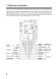
1-2: Tamper monitor:
The contact between pin 1 and pin 2 is broken if the code lock is opened. The contacts can be
integrated into a 24-hour surveillance system for comprehensive monitoring. The connections
can be left unconnected.
3-4, 5-6, 7: Door LED, alarm LED, auxiliary LED:
Programmable LEDs; see “LED indicators”
8: K or A output:
This NPN transistor (open collector with a maximum current of 100 mA at 24 V/DC) can be used
to transfer a signal to other devices when a button is pressed, or when an alarm is triggered
after the door is forced open.
• Keypad alarm (K): Output 8 is switched to GND (-) for 10 seconds each time a button is
pressed. This can be used to turn on lighting and surveillance cameras or send messages
(e.g. to security staff).
• Alarm output (A): Output 8 is switched to GND (-) when a forced door alarm is triggered.
Thissignalcanbeprocessedexternally(e.g.byanexternalsecurityrmoramasteralarm
system).
9-10-11: Output 2:
This output is an auxiliary relay output with a maximum current of 1 A. Output 2 is for user group
2(withthecorrespondingcodes).Usetheprogramcodestoconguretheoutputsettings.The
potential-free contact can be used as an NO (Normaly Open) or NC (Normaly Closed) contact.
It is designed for controlling security or automatic machine control systems.
12: Output 3:
This NPN transistor output (open collector) is designed for additional auxiliary functions. It can
control security systems or an additional 12 V/DC relay. Output 3 is for user group 3 (with the
corresponding codes). This output is switched to GND (-) when it is activated. The output can
tolerateamaximumcurrentof 100mAat 24V/DC.Usetheprogram codestocongurethe
output settings.
10