
Instructions

7. Electrical connection
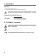
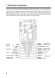
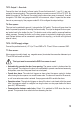
Connect the 16 cables according to the following diagram. Alternatively, you can release the pin
strip and connect a separate connector directly to the circuit board. The circuit board features 6
additional screw contacts (T1: open, T2-4, T5-7). Insert the ends of the cables into these con-
tacts and tighten the screws. You can also use the 3 jumper contacts. Ensure that the soldering
jointsarereliableandstripallopencablecontactstoasufcientlength.
TAMPER
MONITOR
GREEN LED
RED LED
RED AUXILIARY LED (-)
POWER LED OR
ALARM OUTPUT
EMERGENCY
CODE - OUTPUT
GND
COMMUNICATION
INHIBITING INPUT
OUTPUT 3
OUTPUT 2
WHITE
/ORANGE
BROWN
YELLOW GREEN (-)
ORANGE
WHITE/RED
BLUE (NO)
WHITE/
BROWN (COM.)
PURPLE (NC)
}
{
{
{
RED
BLACK
GREY (-)
GREEN (+)
LIGHT BLUE (-)
YELLOW (+)
WHITE
PINK
8