Pure Sine Wave Inverter Charger Renogy 1000W | 2000W Pure Sine Wave Inverter Charger Manual 1 2775 E. Philadelphia St., Ontario, CA 91761 1-800-330-8678 Version 1.
Important Safety Instructions Please save these instructions. This manual contains important safety, installation, and operating instructions for the inverter. The following symbols are used throughout the manual: WARNING: Indicates a potentially dangerous condition. Use extreme caution when performing this task. CAUTION: Indicates a critical procedure for safe and proper operation of the inverter. NOTE: Indicates a procedure or function that is important to the safe and proper operation of the inverter.
Battery Safety • Do NOT let the positive (+) and negative (-) terminals of the battery touch each other. • Use only sealed lead-acid, flooded, or gel batteries which must be deep cycle. • Explosive battery gases may be present while charging. Be certain there is enough ventilation to release the gases. • Be careful when working with large lead acid batteries. Wear eye protection and have fresh water available in case there is contact with the battery acid.
Table of Contents General Information......................................................................................................... 5 Included Components ..................................................................................................... 6 Additional Components ................................................................................................... 6 Identification of Parts (Top View) ....................................................................................
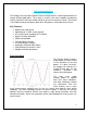
General Information The Renogy Pure Sine Wave Power Inverter Charger delivers superior performance for remote off-grid applications. The inverter is of pure sine wave capable of producing cleaner, smoother, and more reliable electricity for a user’s electronic needs. The inverter is also able to charger the battery bank when AC power is connected to the inverter.
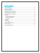
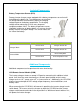
Included Components Battery Temperature Sensor (BTS) Renogy inverter chargers come equipped with a battery temperature sensor that will help prolong the battery life. The temperature sensor allows the charge controller to continuously adjust the charging voltage based on the battery temperature. The charging voltage will be reduced by 0.1V for every degree of temperature above 104℉.
If commands from the two boards conflict with each other, the following priorities will automatically take place: Power Saver On > Power Saver Off > Power Off Both panels in the off position will power the inverter off. NOTE: When the inverter is in Battery-priority mode, finishes a complete charging cycle, and switches to inverter mode, “AC: Abnormal” will be displayed.
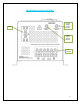
Identification of Parts (Top View) Main Switch Board Battery Charger Type Legend Current Control Legend LED Indicator and Control Knobs Main Control Switch (3 modes) Numerical Battery Type Selector Charging Current Control + Legend Battery Type Charge Value 8
Identification of Parts (AC Side) GFCI Inverter Output Circuit Breaker Charger Input Circuit Breaker AC Terminal 9
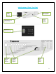
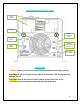
Identification of Parts (DC Side) DC Terminals DC Fan Auto Generator Start RJ45 LCD Remote Battery Temperature Sensor Port DIP Switches Grounding Terminal Installation WARNING: Make sure inverter is in the off position before connecting anything. CAUTION: Do not over-torque or over tighten the terminals. This could potentially damage the unit CAUTION: Refer to the technical specifications for max wire sizes on the controller and for the maximum amperage going through wires.
Location Recommendations WARNING: Never install the inverter in a sealed enclosure with flooded batteries. Gas can accumulate and there is a risk of explosion. Ensure installation follows the following guidelines: 1. Cool, dry, well-ventilated area—Heat is the worst enemy for electronic equipment. Inverters must be in an area where the fans are not blocked or where they are not hit directly by the sun.
*For this Renogy Inverter Charger, the battery bank will be 12 volts direct current (12 VDC) Example 700 Watts to run microwave using the batteries as if it was a 12VDC microwave requires 58 Amps A Microwave = 700 Watts 12V battery bank Load Operation = 3 hours 700 Watts / 12 Volts = 58 Amps Now that amps have been determined, the amps hours need to be determined. The microwave will be used for approximately 3 hours a day.
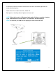
DC Wiring CAUTION: We recommend installing the inverter as close as possible to the battery bank. The torque rating for the DC terminal is 12.5NM-20.5NM. The torque rating suggested is 17NM. Inverter 1000W 2000W Cable Size (10 feet distance) AWG 4-1/0 AWG 2/0 AC Wiring WARNING: AC Output should NEVER be connected to public power or a generator. CAUTION: When connecting to an AC source we recommend using 6-10AWG wire and wiring just like the picture below. (120V Single Phase Wiring Only).
NOTE: The input terminals of the inverters have large capacitors connected to them. Once a positive and negative wire are connected to the terminals, it will complete the circuit, and commence drawing a heavy current momentarily. As a result, there may be a sparking occurring even if the inverter is in the off position. To minimize sparking, it is recommended that the user have the appropriate size wire feeding into the inverters and/or install an external fuse leading into the inverter.
5 6 7 8 9 Gel 2 Flooded Lead Acid Calcium (Open) Equalization Not Used 14.4V 14.8V 15.1V 13.8V 13.8V 13.6V 15.5V for 4 hrs. N/A N/A Battery Charging Stages Bulk Stage: The charger will supply constant current until the battery voltage reaches the boost voltage. The software will calculate the time charging began up until the battery voltage reaches 0.3V below the boost voltage. It uses this time to as T0 and T0×10 = T1.
most batteries this could cause damage. Please refer to the batteries owner’s manual or contact the manufacturer to see if this stage is needed. Transfer Switch The inverters come with a 20A/30A transfer switch that allows the inverters to switch between AC shore power and AC inverter mode (DC to AC) in a matter of 10 milliseconds. The inverter will automatically switch to battery power when the AC input voltage drops below 90VAC.
The inverter can be set to output 50Hz or 60Hz using this switch SW 5 (Battery/AC Priority): When the inverter is set to battery priority (Position 1) it will invert power from the battery bank to the AC outlets until the low voltage set point is reached. If there is an AC source connected while under battery priority it will charge the battery after the low voltage is reached and use the AC source to power the AC outlets. When the battery is fully charged, the inverter will switch to battery power.
inverter will start supplying power. NOTE: To activate this mode DIP switch 3 must be set to position 1. The idle consumption when using power saver mode is approximately 8 watts.
The Renogy Inverter Charger can start up a generator when the low battery voltage set point is reached. The auto gen start feature will only work with generators compatible with this feature. Inverter Troubleshooting The following table will help identify the inverters failure. Use the LED lights and compare with the following graph.
Indicator Under Voltage Alarm Over Voltage Alarm Over Load Protection Short Circuit Other Considerations Battery cables are connected to the inverter but it does not power on There is no AC output or LED indicator lights on The battery charger turns off while connected to an external AC source Idle draw from inverter The inverter is only able to run AC loads for a short period of time Troubleshoot Use a multi-meter to check the voltage of the battery.
External Fusing Fusing is a recommended in PV systems to provide a safety measure for connections going from panel to controller and controller to battery. Remember to always use the recommended wire gauge size based on the PV system and the controller. NEC Maximum Current for different Copper Wire Sizes #AWG 16 14 12 10 8 6 4 2 0 Max.
AC Input Frequency Range 57-65±0.3Hz for 60Hz Low Voltage Disconnect 80V/90V±4% Low Voltage Reconnect 90V/100V±4% High Voltage Disconnect 140V±4% High Voltage Reconnect 135V±4% Short Circuit Protection (AC Output) Circuit Breaker Bypass Breaker Rating Dimension 20A 30A 15 x 8.5 x 7 in 381 x 215.9 x 177.8 mm 20.5 x 8.5 x 7 in 520.7 x 215.9 x 177.8 mm 35.27 lbs. 40.9 lbs.