Battery Power Inverters Renogy 500W | 1000W | 2000W Pure Sine Wave Inverter Manual 1 2775 E. Philadelphia St., Ontario, CA 91761 1-800-330-8678 Version 1.
Important Safety Instructions Please save these instructions. This manual contains important safety, installation, and operating instructions for the inverter. The following symbols are used throughout the manual: WARNING: Indicates a potentially dangerous condition. Use extreme caution when performing this task. CAUTION: Indicates a critical procedure for safe and proper operation of the inverter. NOTE: Indicates a procedure or function that is important to the safe and proper operation of the inverter.
Battery Safety • Do NOT let the positive (+) and negative (-) terminals of the battery touch each other. • Use only sealed lead-acid, flooded, or gel batteries which must be deep cycle. • Explosive battery gases may be present while charging. Be certain there is enough ventilation to release the gases. • Be careful when working with large lead acid batteries. Wear eye protection and have fresh water available in case there is contact with the battery acid.
Table of Contents General Information ...................................................................................................... 5 Included Components................................................................................................... 6 Identification of Parts (AC Side)................................................................................... 7 Identification of Parts (DC Side)...................................................................................
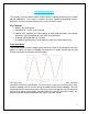
General Information The Renogy Pure Sine Wave Power Inverter delivers superior performance for remote off-grid applications. The inverter is of pure sine wave capable of producing cleaner, smoother, and more reliable electricity for a user’s electronic needs. Key Features • • • • • Robust and sleek design Optimized for 12 VDC system voltage Special LED indicators for under-voltage or over-temp protection, over-voltage protection, over-load protection, and short circuit indication.
Included Components The Renogy Pure Sine Wave Battery Inverters will be shipped with inverter cables and select models will include a key chain remote for powering the inverter on or off.
Wireless Remote Feature The 1000W and 2000W inverters will feature a wireless keychain remote for powering the inverter loads on or off. The remote works for a maximum distance of 170 feet from the inverter’s location and it includes a clip for easy attaching.
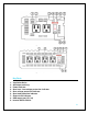
Figure 2: 1000W Inverter Figure 3: 2000W Inverter Key Parts 1. 2. 3. 4. 5. 6. 7. 8. 9.
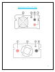
Identification of Parts (DC Side) Figure 4: 500W Inverter Figure 5: 1000W Inverter 9
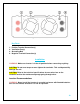
Figure 6: 2000W Inverter Key Parts 1. 2. 3. 4. Positive Terminal Connection(s) Ventilation Fan(s) Grounding Bolt Negative Terminal Connection(s) Installation WARNING: Make sure inverter is in the off position before connecting anything. CAUTION: Do not over-torque or over tighten the terminals. This could potentially damage the unit CAUTION: Refer to the technical specifications for max wire sizes on the controller and for the maximum amperage going through wires.
Ensure installation follows the following guidelines: 1. Cool, dry, well-ventilated area—Heat is the worst enemy for electronic equipment. Inverters must be in an area where the fans are not blocked or where they are not hit directly by the sun. They should be in an area free of any kind of moisture and allow for clearance of at least 10” around the unit to provide for adequate ventilation. 2.
*For this Renogy inverter, the battery bank will be 12 volts direct current (12 VDC) Example 700 Watts to run microwave using the batteries as if it was a 12VDC microwave requires 58 Amps A Microwave = 700 Watts 12V battery bank Load Operation = 3 hours 700 Watts / 12 Volts = 58 Amps Now that amps have been determined, the amps hours need to be determined. The microwave will be used for approximately 3 hours a day.
DC Side Connection WARNING: The Renogy Pure Sine Wave Inverters are suitable for 12V battery bank systems ONLY. Not following the minimum DC requirement will cause irreversible damage to the unit. CAUTION: Be careful of the positive and negative poles. Reversing the poles might cause permanent damage to the inverter. It will surely blow the internal fuse. NOTE: Damage to the Renogy inverters due to reverse polarity is NOT covered by warranty.
2. Unscrew inverter terminals and connect battery connections. Then tighten.
Operation Assuming proper battery connection, the inverter is now ready for use. AC Side Operation 1. Connect electronic devices to electrical socket(s) on inverter. Flip inverter power to ON position (on AC side) NOTE: The red “power” indicator will illuminate. 2. When finished switch AC devices off FIRST, then turn off inverter switch. NOTE: The red “Over-heat / Low-voltage indicator will flash very quickly and the user will hear a quick beep when shutting down the inverter. This is normal behavior.
USB Operation The Renogy inverters are equipped with a unique USB feature where the user is able to plug their USB devices for charging purposes. This feature is a simple “plug and play”. NOTE: USB operation is not compatible with the Apple Lightning Connector. Instead the AC plug with the Apple Adapter should be used. Inverter Indicators The Renogy inverters are equipped with red LED indicators to let the user know the status of the inverter.
Short Circuit Indicator (AUDIBLE ALARM) If the inverter experiences an internal short circuit, it will sound the alarm and turn on the red indicator. Inverter Troubleshooting Indicator Under Voltage or Over Heat Protection Troubleshoot Use a multi-meter to check the voltage of the battery. Make sure the battery voltage is not below the rated specification of the inverter. The inverters have an input requirement of at least 11 ± 0.5 volts. Disconnect battery if necessary.
Short Circuit A short might occur down the DC line connecting to the inverter. Check the battery connections going to the inverter and ensure that there is continuity. In the event that there is an in-line fuse installed, check to make sure the fuse has not blown. Reset the inverter by turning it off for approximately 5 seconds and powering it back on. Other Considerations Radio or television experience some interference. Battery cables are connected to the inverter but it does not power on.
Idle draw from inverter When the inverter is switched on, the circuitry inside is activated. Even if there is no load on the AC side of the inverter, users will experience a small amount of current draw to keep the circuitry within the inverter ready to power. It is recommended to turn off the inverter when not in use. External Fusing Fusing is a recommended in PV systems to provide a safety measure for connections going from panel to controller and controller to battery.
Technical Specifications Model Rated Power RNG-500W RNG-1000W RNG-2000W 500 W 1000 W 2000 W Rated Voltage 12 VDC Rated Voltage Range 11 V – 15V Input Voltage DC ≥ 10V ± 0.5V Over-Voltage Range 16V ± 0.5V Output Voltage AC 110V ± 10% Efficiency 85% Output Frequency Self-Consumption 60 Hz .52 A 1.2 A Waveform Pure Sine Wave USB outlet 5V, 2A Operation Temperature Dimensions Weight AC Sockets 1.7 A -10°C (+)50°C / 14°F 122°F 8.87 x 4.75 x 2.75 in 225 x 120 x 69 mm 3.50 lbs 1.