
Manual

06
15
16
7
17
18
11
9
10
8
13
12
14
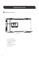
Left View (Uncovered)
6
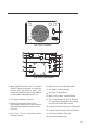
Left View (Covered)
Main ON/OFF Switch: This is a simple
ON/OFF switch to be able to control the
inverter with the plate in place. The
wiring is connected to the Terminal Block
on the inside of the plate seen in 13.
RJ11 Port: Port for connecting Wired
Remote Control
Dry Contact Relay Port: NC, C, NO ports
for connecting generators and making
use of the Auto-Gen Start feature.
Battery Temperature Sensor Port:
Non-polarity sensitive port that connects
the included temperature sensor to the
PCL unit.
DC Negative Battery Terminal
Rj45 Port for Future Development
AC Output Terminal Block
AC Input Terminal Block
Main Power Switch Terminal Block
Inverter Output Protection Circuit Breaker
Inverter Input Protection Circuit Breaker
DC Positive Battery Terminal
Fans that dissipate heat
6.
7.
8.
9.
12.
11.
10.
13.
14.
15.
16.
17.
18.