BATTERY POWER INVERTERS 1000W | 2000W | 3000W Version 2.
Important Safety Instructions Please save these instructions. This manual contains important safety, installation, and operating instructions for the inverter. The following symbols are used throughout the manual: WARNING CAUTION NOTE Indicates a potentially dangerous condition. Use extreme caution when performing this task. Indicates a critical procedure for safe and proper operation of the inverter. Indicates a procedure or function that is important to the safe and proper operation of the inverter.
Battery Safety Do NOT let the positive (+) and negative (-) terminals of the battery touch each other. Use Sealed Lead Acid, AGM, Flooded, Gel, or Lithium batteries which must be deep cycle. Explosive battery gases may be present while charging. Be certain there is enough ventilation to release the gases. Be careful when working with large lead acid batteries. Wear eye protection and have fresh water available in case there is contact with the battery acid.
Table of Contents General Information Product Description Product Overview 04 05 Identification of Parts (AC Side) 05 Identification of Parts (DC Side) 06 Dimensions 07 Included Components 08 Optional Components 08 Installation 09 Location Recommendations 10 Sizing your Battery Bank 10 Wiring 03 04 11 Grounding 11 DC Wiring 11 AC Wiring 15 Fusing 16 Operation 17 AC Side Operation 19 LED Overview 19 Wired Remote 19 DIP Switches 19 Troubleshooting 20 Technical Specifi
General Information Product Description The Renogy PGH1 inverter transforms the DC power stored in batteries into standard household AC power for consumer electronic needs. It features an ECO power-saving mode in order to conserve your system's energy and even has a switch to change the frequency between 50Hz/60hz. As a pure sine wave inverter, it is capable of producing cleaner, smoother, quieter, and more reliable electricity to operate fans, lights, and other electronics without interference.
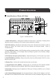
Product Overview Identification of Parts (AC Side) 1 2 3 GF L N 50Hz ECO 60Hz Nor. ON OFF REM. AC OUTPUT AC OUTPUT COMM. REMOTE 7 6 4 5 G 9 8 Figure 1: 3000W Inverter 1. Power LED (Green) - Solid Green indicates normal power on operation. Flashing Green indicates inverter is powered in ECO power saving mode and is pulsing. 2. GF LED (Yellow) - Indicates an interruption in the circuit. Shut down the inverter to clear or review AC wiring.
Identification of Parts (DC Side) 1 2 3 4 Figure 2: 3000W Inverter 1. 12VDC M8 Negative Battery Terminal - Negative 12V DC is written above the terminal. 2. Ventilation Fans - Automatic fans that dissipate heat inside the inverter. They that are temperature controlled. 3. 12VDC M8 Positive Battery Terminal - Positive 12V DC is written above the terminal. 4. M4 Grounding Lug - Connect to grounding point which will vary depending on install.
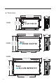
Dimensions L G AC OUTPUT 50Hz Nor. ECO COMM. 60Hz [6.5in] 166.0mm GF REMOTE L N G AC OUTPUT AC OUTPUT 234.5mm [9.2in] 50Hz Nor. ECO COMM. 60Hz GF REMOTE L N G AC OUTPUT AC OUTPUT 50Hz Nor. ECO COMM. 60Hz GF REMOTE [11.4in] 290.3mm [3.8in] 96.0mm [15.8in] 401.0mm [12.4in] 351.5mm [3.8in] 96.0mm [18.6in] 472.5mm [16.7in] 423.5mm 3000W 29,3 [7.6in] 193.0mm 234.5mm [9.2in] 249.0mm [9.8in] 07 249.0mm [9.8in] 2000W 8,9 1000W N 54,2 [2.8in] 71.0mm [13.4in] 340.
Included Components The PGH1 inverter will include a wired remote controller that can power the inverter ON or OFF. In addition, the 1000W and 2000W models will include inverter cables. Inverter Model Gauge 1000W 4 AWG 2000W 4 AWG * 2 3000W Cables not included. 4/0 Recommended Wired Remote Control The Wired Remote Control for the inverter gives users the opportunity to power on/off the inverter from a distance. Giving you approximately 16.
Installation WARNING Make sure inverter is in the off position before connecting anything. CAUTION Do not over tighten the terminals. This could potentially damage the unit. Location Recommendations WARNING Never install the inverter in a sealed enclosure with flooded batteries. Gas can accumulate and there is a risk of explosion. Ensure installation follows the following guidelines: 1. Cool, dry, well-ventilated area — Heat is the worst enemy for electronic equipment.
Sizing your Battery Bank Battery types and capacity relate to overall inverter performance. To size a battery bank, you need to identify the loads that you will be utilizing, as well as an estimate (hours/day) you will be using the load. The inverter is only compatible with 12V battery banks and oversizing should be considered due to efficiency losses. 1.
Wiring Grounding CAUTION WARNING Do not over-tighten the M4 Ground Screw. The recommended torque is 1.5~2.0N-m / 13~18.2 lbf-in At no point should the chassis ground and the neutral conductor of the inverter be bonded. Bonding the chassis ground and the neutral conductor of the inverter or connecting the inverter to household or recreational AC distribution wiring will damage the unit and void the warranty.
Make sure your battery bank is rated for 12V. Batteries that are 6V may be put in series to create a 12V battery bank. 12V batteries may be connected in parallel prior to connecting to the inverter DC terminals. When joining batteries together, they must be the same chemistry, voltage, and are also recommended to be the same level prior to combining.
1.
2.Remove Cap, then unscrew inverter terminals and connect battery connections. Then tighten.
AC Wiring WARNING NOTE All AC Wiring should be approved by an electrician for RV or Marine applications. Do not connect the AC Output to a power source like a generator/shore power. Irreversible damage may occur. Do not over-tighten the screws in the AC Terminal Cover or Terminal Block. The recommended torque for the M3 terminal cover screws is .64 ~ 1.0N-m / 5.7 ~ 9.1 lbf-in The recommended torque for the M4 terminal block is Max 0.98N-m / 8.
Fusing The following are recommended fuse minimums: Model Fuse Minimum AWG Minimum 1000W 100A 4 AWG 2000W 200A 2 AWG 3000W 300A 4/0 16
Operation Assuming proper connection, the inverter is now ready for use. To operate using the AC Outlets: AC Side Operation 1.Connect electronic devices to electrical socket(s) on inverter. Flip inverter power to ON position (on AC side) 2. When finished, switch AC devices off FIRST, then turn off inverter switch 3. Turn the device’s power switch on to begin normal use 4.
Wired Remote CAUTION The wired remote will only operate when REM mode is pressed on the inverter. The wired remote control is an alternative way to power on or off your inverter from a distance. To operate: 1.Make sure the push button on the wired remote is not pressed 2.Flip the inverter switch to REM mode 3.Connect the remote wire to the REMOTE port on the inverter model 4.To confirm success, press the power button to power on the inverter via remote. GF ECO 60Hz Nor. AC OUTPUT COMM.
DIP Switches The DIP switches allow you to control the inverter’s ac output frequency or power up in an ECO power saving mode. For DIP switch changes to take effect you must: 1.Shut down the inverter via power button or remote 2.Make the desired dip switch change 3.Power On the inverter via power button or remote 4.DIP Switch changes have taken effect Frequency DIP Switch You can change your AC output frequency between 50Hz or 60Hz depending on your location. By default, the USA uses 60Hz.
Troubleshooting Indicator Potential Issue Troubleshoot The battery is depleting faster than it is being charged. Lower Battery Undervoltage Alarm the inverter load power or disconnect the load to let the Fault LED Lit battery charge up to 12.0V at least. and Alarm Beeps Battery Overvoltage The battery is at a higher than normal voltage, perhaps from being charged. Use a multi-meter to confirm the voltage and Alarm disconnect any chargers.
Technical Specifications Model Continuous Power PGH1-10111S PGH1-20111S PGH1-30111S 1000 W 2000 W 3000 W Input Voltage 12V DC Output Voltage Peak Surge 110VAC ± 10% 2000 W 6000 W 4000 W Efficiency >90% Frequency 50 Hz / 60Hz (adjustable) < 3% Linear Load Total Harmonic Distortion < 5% Non-linear Load < 3A No Load Consumption < 1A High Voltage Disconnect 15.5V ± 0.5V DC 16V ± 0.3V DC Battery Under-voltage Alarm 10.5V ± 0.5V DC 11V ± 0.3V DC Low Voltage Shutdown 10.0V ± 0.
Wired Remote Control List dimensions 2.8 x 4.3 x 1.3 in / 70 x 110 x 31.8 mm Wire length 16.4 ft This equipment has been tested and found to comply with the limits for a class B digital device, pursuant to part 15 of the FCC Rules. These limits are designed to provide reasonable protection against harmful interference in a residential installation.
RENOGY.COM Renogy reserves the right to change the contents of this manual without notice. US 2775 E Philadelphia St, Ontario, CA 91761, USA 909-287-7111 www.renogy.com support@renogy.com CN 苏州高新区科技城培源路1号5号楼-4 JP https://www.renogy.jp supportjp@renogy.com CA https://ca.renogy.com supportca@renogy.com AU https://au.renogy.com supportau@renogy.com UK https://uk.renogy.com supportuk@renogy.com DE https://de.renogy.com supportde@renogy.com 400-6636-695 https://www.renogy.cn support@renogy.