
How to Guide


05
Product Overview
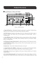
Identification of Parts (AC Side)
Figure 1: 3000W Inverter
1. Power LED (Green)
- Solid Green indicates normal power on operation. Flashing Green
indicates inverter is powered in ECO power saving mode and is pulsing.
2. GF LED (Yellow)
- Indicates an interruption in the circuit. Shut down the inverter to clear or
review AC wiring. The inverter does not have Neutral and Ground bonded. Refer to
Troubleshooting.
3. Fault LED (Red) + Alarm
- Solid Red light indicates a system fault due to either overheating,
overload, undervoltage, or over-voltage. Alarm sounding is typical for a low battery voltage.
Refer to Troubleshooting.
5. ON/OFF/REM Power Button
- Main power button that can switch between ON, Off, or be in
Remote control mode.
7. Communication Port (RS485)
- Optional port for connecting the BT-2 Module (Model:
RCM-BT2) or Monitoring Screen (Model: RMS-PGH). Requires separate purchase.
8. AC Outlets
- Directly plug in AC appliances. Utilize up to 8.3Amps (1000W) or up to 15amps
(2000W/3000W).
9. AC Terminal Block (Covered)
- Use the terminal block to utilize the full wattage in 110V AC
50Hz/60Hz for the 2000W/3000W models. 1000W model can use full wattage using the AC outlets.
6. Remote Port
- Connect the included wired remote onto this port.
4. DIP Switches (Frequency/Power Saver)
- Adjust the frequency or ECO power saver mode.
1 2 3
5
4
9 8
7 6
AC OUTPUT AC OUTPUT
L N G
ON
OFF
REM.
REMOTE
ECO
GF
COMM.
50Hz
60Hz Nor.