Dual Input DC-DC On Board Battery Charger w/ MPPT 30A | 50A Version 1.
Important Safety Instructions Please save these instructions. This manual contains important safety, installation, and operating instructions for the DCDC Battery Charger. Do not operate the Battery Charger unless you have read and understood this manual and the charger is installed as per these installation instructions. Renogy recommends that the charger be installed by a qualified professional. Store it in a safe place.
General Safety DANGER In the event of fire,use a fire extinguisher that is suitable for electrical devices. WARNING Only use the product as intended. Make sure all connections going into and from the product are tight Disconnect the product from the battery ——each time before cleaning and maintenance ——before a fuse change (only by specialists) Do NOT allow water to enter the product ——Detach all connections. ——Make sure that no voltage is present on any of the inputs and outputs.
Safety when connecting the product electronically DANGER Danger of fatal electric shock! For installation on boats: If electrial devices are incorrectly installed on boats,this can lead to corrosion damage on the boat. Have the product installed by a qualified (boat) electrician. If you are working on electrical systems,ensure that there is somebody close at hand who can help you in emergencies. WARNING Make sure that the cables has a suffcient cross-section.
Battery Safety WARNING Batteries may contain aggressive and corrosive acids. Avoid battery fluid coming into contact with your body. If your skin does come into contact with battery fluid,thoroughly wash that part of your body with water. If you sustain any injuries from the acids,contact a doctor immediately. CAUTION When working on batteries,do not wear any metal objects such as watches or rings. Lead acid batteries can cause short circuits which can cause serious injuries.
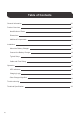
Table of Contents General Information 06 Product Overview 07 Identification of Parts 07 Dimensions 09 Additional Components 10 Installation Mount the Battery Charger 11 Connect the Battery Charger 14 Typical Setup 15 Cable and Fuse Sizing 15 Operation 05 11 16 LED Indicators 16 Charging Logic 17 Solar Charger Algorithm 18 Trouble shooting 21 Technical Specification 22
General Information The Renogy Dual Input DC-DC On Board Battery Charger w/ MPPT is designed to charge your service battery to 100% from two inputs: solar and alternator.
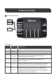
Product Overview Identification of Parts BVS+ 5 1 6 7 8 2 BVSIGN+ 4 3 9 10 11 12 13 Key Parts 07 # Labeling 1 PV+ Positive (+) input terminal for the PV Array. Requires ring terminal 2 ALT+ Positive (+) input terminal from the Starter Battery 3 OUT+ Positive (+) output terminal for House Battery 4 NEG- Common Negative (-) Terminal for Solar Panel Array, Starter Battery, and House Batt 5 RS485 Communication port for app and monitoring screen; future development.
Key Parts Labeling # Description Ignition Signal Input port for triggering the battery charger for smart alternators. IGN wire recommended 18-16AWG . IGN+ 8 Standard/Traditional Alternator –has a fixed voltage when charging (Do not connect IGN wire) Smart Alternator—has a controlled charging output based on operating conditions Variable. (Requires IGN signal wire). 9 TYPE Battery type push button. Change the LED to the matching battery type of your application.
Additional Components Additional components included in the package: Battery Temperature Sensor The proper battery charging voltage is important for optimum battery performance and longevity. This Remote Temperature Sensor measures temperature at the battery, allowing the DC-DC charger to use this data for accurate temperature compensation and charge voltage adjustment. NOTE No temperature compensation when charging lithium battery.
Installation Mount the Battery Charger DANGER Never mount the product in areas where there is a risk of gas or dust explosion. CAUTION Ensure a secure stand! The product must be set up and fastened in such a way that it cannot tip over or fall down. NOTICE Do not expose the product to any heat source (such as direct sunlight or heating). Avoid additional heating of the product. Set up the product in a dry location protected from splashing water.
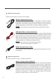
Connecting Temperature Sensor The temperature sensor will have a green housing connector on one end and a metal probe on the other. Simply align and connect the green housing to the BTS terminal on the DCDC. Place the probe end of the sensor near or on top of the battery to monitor temperature in the area. Connecting IGN Signal Wire Connect the positive line to one of green housing ports on the IGN port. You will need to open the wire terminal utilizing the screws on top of the green housing.
Connecting Battery Voltage Sensor Connect the Battery Voltage Sensor connector to the BVS port. Connect the positive line to the left side of the green housing and then connect the negative line to the right side of the green housing. You will need to open the wire terminal utilizing the screws on top of the green housing. You will then need to place the bare wire end onto the respective battery terminal for accurate voltage sensing.
Connect the Battery Charger WARNING Do not reverse the polarity. Reverse polarity of the battery connections can cause injury and damage the device. CAUTION Avoid coming into contact with the battery fluid under any circumstances. Batteries with a cell short circuit should not be charged as explosive gases may form due to the battery overheating. Be careful not to over-torque the terminals on the DCDC. Over-torquing may cause irreparable damage. Do not exceed 16 N-m / 3.
Solar Panel Typical Setup Solar Ad Adapter Kit DC-DC MPPT Charger Common NEG- PV+ MC-4 INLINE Fuse ANL Fuse ING(D+) Signal Wire for smart alternator Cables to Starter BATT Starter BATT+ House BATT+ Cables to House BATT Alternator House BATT+ Starter BATT+ ANL Fuse NOTE Be careful not to over-torque the terminals on the DCDC. Over-torquing may cause irreparable damage. Do not exceed 16 N-m / 3.
Operation LED Indicators Solar Charging Indicator Color Status ON Slow Flashing Single Flashing Red Fast Flashing Double Flashing OFF Description Bulk charge (MPPT) Boost charge Float charge Equalizing charge Current-limit charge Not charging Service Battery Indicator Color Green Yellow Red NOTE Status ON ON ON Slow Flashing Fast Flashing Description Battery Full Battery voltage normal Battery undervoltage Battery over discharged Battery over voltage/ over temperature The Charging Indicator may change
Charging Logic Alternator Input 1. Connect alternator with starting battery and service battery (No solar panel, or night time) 1.1 The DCDC battery charger will connect or disconnect the service battery according to the starting battery voltage. Alternator Type Starting Battery Voltage Cut-in Cut-off Traditional Alternator >13.2V, for 15 seconds <12.7V Smart Alternator >12.0V, for 15 seconds <11.5V 1.2 The DCDC will stop charging if the alternator input voltage is higher than 16.
a. DCDC30: 15A from alternator, up to 15A from solar for a total of up to 30A. b. DCDC50: 25A from alternator, up to 25A from solar for a total of up to 50A. 4. Operating Temperature 4.1 The DCDC will lower the output power when its internal temperature is in the range from 65℃ to 80℃. It will stop charging when the temperature is higher than 80℃, and recover to charge when the temperature is lower than 60℃. 4.
Limiting Effectiveness Temperature is a huge enemy of solar modules. As the environmental temperature increases, the operating voltage (Vmp) is reduced and limits the power generation of the solar module. Despite the effectiveness of MPPT technology, the charging algorithm will possibly not have much to work with and therefore there is an inevitable decrease in performance.
Constant Charging: When the battery reaches the constant voltage set point, the charger will start to operate in constant charging mode, where it is no longer MPPT charging. The current will drop gradually. This has two stages, equalize and boost, and they are not carried out constantly in a full charge process to avoid too much gas precipitation or overheating of the battery. Boost Charge: Boost stage maintains a charge for 2 hours by default.
Troubleshooting CAUTION NOTE Do not open the device. You risk exposing yourself to an electric shock by doing this. If you have detailed questions about the battery charger, please contact our customer support (addresses on the back of the instruction manual). Solar Charging Indicator OFF Troubleshoot Ensure that the Solar Panel is not being shaded (by a tree etc.) Verify the Solar Panel voltage is higher than 15V threshold with a multi-meter and check the electric connections.
Technical Specification Product RBC30D1S System Voltage 12VDC 9~16VDC Battery Voltage Range Maximum Charging Current Battery Type Service Battery Charging Mode Charging Efficiency Max. Solar Input Voltage Max. Solar Input Power Alternator Input Voltage Max. Alternator Input Power Temp.
Battery Charging Parameters Battery Type Over-voltage Warning Charging Limit Voltage Over-voltage Recover Boost Charge Voltage Float Charge Voltage Equalization Voltage Boost Return Voltage Under Voltage Warning Under Voltage Recover Over-discharge Warning Over-discharge Recover Boost Duration Equalization interval Equalization Duration NOTE SEALED/AGM GEL FLOODED LI (LFP) USER 16 V 15.5 V 15 V 14.6 V 13.8 V ----13.2 V 12V 12.2V 11.1V 12.6 V 2 hours --------- 16 V 15.5 V 15 V 14.2 V 13.8 V ----13.
RENOGY.COM Renogy reserves the right to change the contents of this manual without notice. US CN 2775 E Philadelphia St, Ontario, CA 91761, USA 909-287-7111 www.renogy.com support@renogy.com 苏州高新区科技城培源路1号5号楼-4 400-6636-695 https://www.renogy.cn support@renogy.cn JP https://www.renogy.jp supportjp@renogy.com CA https://ca.renogy.com supportca@renogy.com AU https://au.renogy.com supportau@renogy.com UK https://uk.renogy.com supportuk@renogy.com DE https://de.renogy.com supportde@renogy.