REGO DC-DC Battery Charger 12V 60A VERSION A0 input DC-DC Battery Charger output QUICK GUIDE
Contents Package Contents•••••••••••••••••••••••••••••••••••••••••••••••••••••••••••••••••••••••••••••••••••••••••••••••••••••••••••••••• 01 Wiring Diagram •••••••••••••••••••••••••••••••••••••••••••••••••••••••••••••••••••••••••••••••••••••••••••••••••••••••••••••••••••••• 02 Product Overview ••••••••••••••••••••••••••••••••••••••••••••••••••••••••••••••••••••••••••••••••••••••••••••••••••••••••••••••••• 03 Installation •••••••••••••••••••••••••••••••••••••••••••••••••••••••••••••••••••••••••••••••••••••••
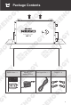
Package Contents input DC-DC Battery Charger output Quick Guide × 1 Renogy Temperature Sensor × 1 (Model: RTSCC) IGN Signal Wire × 1 Screws × 4 REGO DC-DC Battery Charger 12V 60A VERSION A0 input DC-DC Battery Charger output QUICK GUIDE 01
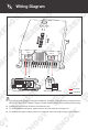
DC-DC B attery Cha rger Wiring Diagram input output + + Positive Starting Battery or DC Generator Service Battery System Negative z This Quick Guide contains important installation, operation, and maintenance instructions for REGO 12V 60A DC-DC Battery Charger. Please read the Quick Guide carefully before using. z Illustrations in the Quick Guide are for reference only. z For more detailed instructions, please refer to the user manual at renogy.com.
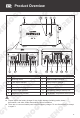
Product Overview 1 2 3 4 1 input DC-DC Battery Charger output DC-DC Battery Charger DC-DC Battery Charger input 5 6 No. CAN output 7 Part 8 9 No.
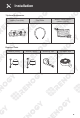
Installation Recommended Components Battery Scenario A: REGO Battery Kit Renogy REGO Lithium Battery Renogy REGO System Combiner Box Battery Adapter Cable (output) ( Anderson PP75 to Anderson 120 Adapter Cable ) Battery Adapter Cable (input) ( Anderson PP75 to Ring Terminal Adapter Cable ) Anderson 120 Anderson PP75 Battery Scenario B: Normal Battery Kit Normal Battery with +/- Bolts + - 04 Battery Adapter Cables (input / output) ( Anderson PP75 to Ring Terminal Adapter Cable )
Installation *Optional Accessories *Battery Fuse (80A) *Battery Voltage Sensor (Model: RVSCC) *Fuse Cable Required Tools Wrench (14mm) Insulation Tape 4 5 6 14mm 14mm 3 10mm 10mm 10mm Measuring Tape 14mm Wrench (10mm) 05
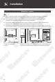
Installation Mounting Location z Risk of explosion! Never install the battery charger in a sealed enclosure with flooded batteries! Do not install in a confined area where battery gases can accumulate. z Place the battery charger on a vertical surface protected from direct sunlight, high temperatures, and water. Make sure there is good ventilation. z The battery charger requires at least 6 inches (150mm) of clearance above and below for proper air flow.
Installation DC-DC Battery Charger Battery Charger Wiring z Please refer to the user manual of the battery charger at renogy.com for the recommended wire gauge and length. z Please make sure that the connections of the Anderson connectors are tight and secure. REGO Battery Kit input input output output Normal Battery Kit For the Output terminal, align the Battery Adapter Cable's Anderson PP75 connectors to the correct orientation and polarity. DC-DC Battery Charger DC-DC Battery Charger STEP-2.
Installation Service Battery Wiring z Please read the user manual of the service battery carefully before installation. z Identify the polarity (positive and negative) on the cables used for the batteries. A reverse polarity contact may damage the unit. z Select a suitable wrench or other tool when tightening the battery bolts to their rated specification. z Please ensure that the Anderson connectors are fully seated and/or the ring terminals are securely connected.
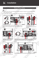
Installation Battery Scenario B: Normal Battery Kit input input DC-DC Battery Charger output DC-DC Battery Charger output Output - - Output + + - 12 12 STEP-3.3 STEP-3.2 Attach the ring terminal of the negative Battery Adapter Cable (output) to the negative battery bolt and tighten with a wrench. For your safety, it is recommended to use a battery fuse (80A).
Installation Input Wiring The battery charger input terminal can be directly connected to the vehicle's starting battery or DC generator. If you want to wire directly to the DC generator, please refer to the user manual of REGO 12V 60A DC-DC Battery Charger at renogy.com for more detailed instructions. z Please check the vehicle's manual to identify the generator type before connecting. If you cannot identify the generator type, please refer to the user manual of battery charger at renogy.
Installation input For your safety, it is recommended to use a battery fuse (80A). Connect the positive Battery Adapter Cable (input) to one end of the battery fuse, and then connect the other end to the positive bolt of the starting battery. DC-DC Battery Charger output Input + STEP-4.3 Attach the ring terminal of the positive Battery Adapter Cable (input) to the positive bolt of the starting battery and tighten with a wrench. + + STEP-4.
Installation Mounting z Please make sure that the battery charger is installed firmly to prevent it from falling off. Place the battery charger against a flat surface and secure it with included screws. DC-DC Battery Charger DC-DC Battery Charger STEP-5.1 Temperature Sensor z The temperature sensor can detect the battery's temperature and update it to the battery charger for charging voltage calibration.
Installation *Voltage Sensor (Optional) The Battery Voltage Sensor is the perfect solution by providing an accurate battery voltage to the battery charger and allowing it to adjust the charging stage precisely resulting in overall extension of your battery life. Identify the polarity (positive and negative) on the cables used for the batteries. A reverse polarity contact may damage the unit. z The voltage sensor ring terminal is M8 (Approx. 5/16").
LED Indicators C ha rg er at te ry C ha rg er STEP-8.3 B at te ry B STEP-8.2 D C -D C D C -D C B STEP-8.1 The Battery indicator flashes green while the service battery system is being charged. D C -D C at te ry C ha rg er Battery Status Indicator Once the service battery system is fully charged, the battery charger stops working and the Battery indicator lights up green and remains solid.
Communication The communication connection is optional. The communication between REGO products allows safe operation, smart control, and close monitoring. Depending on the installation condition, the communication connection needs to be established with backbone or daisy chain topology. Backbone Topology If an RV-C bus is pre-installed in the RV, please follow the backbone topology for the communication connection.
Communication 4321 STEP-9.1 STEP-9.2 Squeeze the crimp area of the Drop Plug with a pair of split joint pliers. Insert the bare wires of the Drop Cable (sold separately) all the way into the wire ports of the Drop Plug (not included) following the Drop Plug pinout. The red PS+ wire goes to pin 1, the white CAN_H wire goes to pin 2, the blue CAN_L wire goes to pin 3, and the black PSwire goes to pin 4.
Communication Daisy Chain Topology If the RV-C bus is not available, please follow the daisy chain topology for the communication connection. Recommended Accessories LP16 Plug (7-Pin) Communication Cable LP16 Terminator Plug (7-Pin) D C -D C er rg BVS ha C BVS ery er rg att B ha C C -D ery C D att B IGN IGN BTS BTS IGN STEP-9.5 Connect REGO devices in series through either of the CAN Communication Ports with the Communication Cables (sold separately). BVS BTS STEP-9.
Operation & Maintenance Operation The battery charger is simple and easy to use. The plug & play design makes the installation easier, and the knob with 5 gears makes the selection of battery type more convenient. The default battery type of the battery charger is AGM/SLD. After the wiring of the battery charger output is completed, please manually set the battery type according to the usage needs.
Renogy Empowered Renogy aims to empower people around the world through education and distribution of DIYfriendly renewable energy solutions. We intend to be a driving force for sustainable living and energy independence. In support of this effort, our range of solar products makes it possible for you to minimize your carbon footprint by reducing the need for grid power. Live Sustainably with Renogy Did you know? In a given month, a 1KW solar energy system will...
RENOGY.COM Visit renogy.com to find the User Manual or get more support via "Contact Us". Renogy reserves the right to change the contents of this manual without notice. Your voice matters! Scan the QR code to submit your feedback on the product. Welcome to join Renogy Power Community by scanning the QR code to install DC Home App. Find your e-warranty here, and more.