MONITORING SCREEN FOR SMART LITHIUM BATTERY SERIES Version 1.
Important Safety Instructions Please save these instructions. This manual contains important installation and operation instructions for the Renogy monitoring screen. Please review and observe these instructions and keep them located near the monitoring screen for further reference. The following symbols are used throughout the manual to indicate potentially dangerous conditions or important safety information. Indicates a potentially dangerous condition. Use extreme caution when performing this task.
General Safety Information DO NOT touch the exposed electrolyte or powder if the battery casing is damaged. Uncovered electrolyte or powder that has contacted skin or eyes MUST be flushed out with plenty of clean water immediately. Seek medical attention afterwards. Please make sure any battery charger or charge controller has been disconnected before working on the battery. DO NOT connect or disconnect terminals from the battery without first disconnecting loads.
Table of Contents General Information 04 Key Features 04 Product Overview 05 Identification of Parts 05 Dimensions 05 Additional Components 06 Installation 06 Preparation 06 Choosing an Installation Location 07 Mounting the Monitoring Screen 07 Connecting to the Battery 11 Operation 13 LCD Information 13 Button Operation 17 Troubleshooting 18 Technical Specifications 20
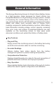
General Information The Renogy Monitoring Screen for Smart Lithium Battery Series is a high precision meter designed for Smart Lithium Iron Phosphate Batteries in off-grid energy storage systems. Instead of measuring the current flowing in/out of the battery bank, it can communicate directly with the battery management system (BMS) and obtain more accurate state of charge (SoC) readings compared to traditional battery monitors.
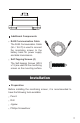
Product Overview Identification of Parts ①② ③ ④ ⑤ ⑧ ⑥ ⑦ ① LCD Screen ⑤ Front Cover Plate ② Page Down Button ⑥ RJ45 Communication Port ③ Page Up Button ⑦ Mounting Hole ④ Power Button ⑧ Snap-Fit Joint Dimensions 1.3in 31.8mm 2.3in 58.5mm 2.8in 70.0mm 4.3in 110.
3.4in 87.5mm Additional Components RJ45 Communication Cable The RJ45 Communication Cable (5m / 16.4 ft) is used to connect the monitoring screen to the battery bank for power supply and data transmission. Self-Tapping Screws (4) The Self-tapping Screws (M2.9 x 13) are used fix the monitoring screen on the mounting surface.
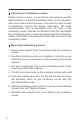
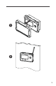
Choosing an Installation Location Please choose a clean, dry, protected, and easily accessible indoor location to install the monitoring screen. It is recommended to mount the monitoring screen at eye level for easy access of operational controls and battery information. The RJ45 Communication Port is accessible from the back of the monitoring screen.
1 2
3 4
5 6
7 Connecting to the Battery Please connect the monitoring screen to the RS485 UP Communication Port of the battery using the included RJ45 Communication Cable to obtain detailed battery information from the battery management system.
If the monitoring screen is used with a parallel battery bank, the communication between paralleled batteries must be enabled. Please connect the RS485 LINK Communication Ports of the former batteries to the RS485 UP Communication Ports of the latter ones using CAT5 (or above) Ethernet straight through cables (not included). The monitoring screen should be connected to the RS485 UP Communication Port of the first battery.
Please avoid too high a voltage difference between paralleled batteries, despite the auto-balancing function, to avoid triggering the over-current protection. In parallel battery banks, the copper cables between each battery should be of equal length to ensure that all batteries in the system can work equally together. It is not recommended to connect too many batteries in parallel if taking advantages of the auto-balancing function. Please leave the battery in shelf mode during installation.
The present voltage indicates the real-time terminal voltage of the battery. If the monitoring screen is used with a battery bank, the present voltage will be the average terminal voltage of the batteries in the battery bank. Present Current (A) The present current indicates the real-time current flowing through the battery or the battery bank. If the charge current is higher than the discharge current, the present current will be a positive value.
Self-Heating Function Status The self-heating function status indicates the operation status of the self-heating function. If the self-heating function is not available or not operating, the self-heating function status will be ‘0’. If the self-heating function is available and operating, the self-heating function status will be ‘H’. Number of Paralleled Batteries The number of paralleled batteries indicates the number of batteries connected in parallel in hexadecimal.
Battery Level The battery level indicates the real-time charge level of the battery relative to its capacity using four battery segments. If the battery is being charged, the battery segments will illuminate one by one repeatedly until the battery is fully charged. If the monitoring screen is used with a battery bank, the battery level will be the average charge level of the batteries in the battery bank.
Error Code Battery Operation Status 04 Battery Over-Voltage Protection / Battery Cell Over-Voltage Protection 05 Battery Under-Voltage Warning 06 Charge Over-Current Warning 07 Discharge Over-Current Warning 08 Battery High Temperature Protection (Charge) 09 Battery Low Temperature Protection (Charge) The communication between paralleled batteries MUST be enabled using CAT5 (or above) Ethernet straight through cables before connecting the battery bank to the monitoring screen to obtain the acc
ing for 1 second to switch the battery or the battery bank to active mode. The backlight will be lit and the LCD Screen will display the present voltage. If no operation is made within 25 seconds, the backlight will go out and the LCD Screen will scroll through the present voltage, present current, capacity, and state of charge. To display a specific parameter, please press the Page Up Button or the Page Down Button repeatedly until the desired parameter shows up.
If the battery information displayed on the monitoring screen is not accurate, please long press the Page Up Button and Page Down Button at the same time for 3 seconds to reset the monitoring screen and refresh the battery information. If the monitoring screen resets frequently or does not display battery information, please reactivate the battery or the battery bank using the Power Button on the monitoring screen.
Technical Specifications Electrical Specifications Operating Voltage 12VDC Operating Current 30mA Power Consumption <1W Operating Temperature -4°F~113°F / -20°C~45°C Voltage Accuracy ±0.1V Current Accuracy ±0.1A Capacity Accuracy ±0.1Ah Certification FCC Part 15 Class B, CE, RoHS Mechanical Specifications Communication Port RJ45 (RS485 Protocol) Display Backlit LCD User Interface 2 Front Panel Menu Buttons, 1 Power Button Mounting Method Wall Mount Dimension 2.8 x 4.3 x 1.
FCC Compliance: This device complies with Part 15 of the FCC Rules. Operation is subject to the following two conditions: (1) this device may not cause harmful interference, and (2) this device must withstand any interference received, including interference that may cause undesired operation. Note: This equipment has been tested and found to comply with the limits for a Class B digital device, pursuant to part 15 of the FCC Rules.
RENOGY.COM Renogy reserves the right to change the contents of this manual without notice. US CN 2775 E Philadelphia St, Ontario, CA 91761, USA 909-287-7111 www.renogy.com support@renogy.com 400-6636-695 https://www.renogy.cn support@renogy.cn JP https://www.renogy.jp supportjp@renogy.com CA https://ca.renogy.com supportca@renogy.com AU https://au.renogy.com supportau@renogy.com UK https://uk.renogy.com supportuk@renogy.com DE https://de.renogy.com supportde@renogy.