
Full Product Manual


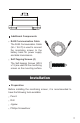


Choosing an Installation Location
Please choose a clean, dry, protected, and easily accessible
indoor location to install the monitoring screen. It is recommend-
ed to mount the monitoring screen at eye level for easy access
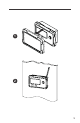
of operational controls and battery information. The RJ45
Communication Port is accessible from the back of the
monitoring screen. Clearance of at least 2 inch (50 mm) behind
the monitoring screen is recommended to allow for the bending
radius of the RJ45 Communication Cable that connects to the
monitoring screen.
Mounting the Monitoring Screen
1.
2.
3.
4.
5.
6.
7.
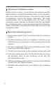
Remove the snap-fit Front Cover Plate from the monitoring
screen.
Use the monitoring screen as a template to mark the screw
holes and trace a cut-out area on the mounting surface with
a pencil.
Cut out a rectangular area for the monitoring screen on the
mounting surface with a jigsaw.
Pre-drill four screw holes on the mounting surface with a drill.
Place the monitoring screen into the cut-out area and align
the Mounting Holes on the monitoring screen with the
pre-drilled screw holes.
Affix the monitoring screen on the mounting surface with the
included four Self-Tapping Screws.
Re-attach the snap-fit Front Cover Plate to the monitoring
screen.