
Full Product Manual

10
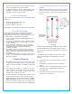
These currents can cause the affected cells to get very hot and
could even damage the module. To protect module from such high
reverse currents
All modules rated greater than 55 Watt have bypass diode already
integrated in the junction box.
In the unlikely event of diode failure Renogy recommends a
qualified service technician be employed to determine if diodes
have failed and to make replacement.
5.4 General Installation
Do not use modules of different configurations in the same system.
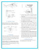
Several modules are connected in series and then in parallel to form
a PV array, especially for application with a high operation voltage. If
modules are connected in series, the total voltage is equal to the sum
of individual voltages. For applications requiring high currents,
several photovoltaic modules can be connected in parallel; the total
current is equal to the sum of individual currents.
Module is supplied with Multicontact connectors (PV-KBT4 and PV-
KST4) to use for system electrical connections. Use the National
Electric Code to determine system wiring size (refer to NEC clause
310), type and temperature rating of conductors to be connected to
the module’s connectors. Wiring connected to the module’s wiring
should be #12 AWG (minimum) and must be temperature rated at
90°C (minimum).
In Canada installation shall be in accordance with CSA C22.1, Safety
Standard for Electrical Installations, Canadian Electrical Code, Part
1.
The cross section area of cable and the capacity of connector must
be selected to suit the maximum system short circuit current,
otherwise the cable and connector will be overheated under large
current. Refer to NEC for details.
Module overcurrent protection, rated for DC use fuses
5.5 Grid Connected Electrical System
The DC electrical energy generated by photovoltaic systems may
also be converted to AC and connected to a utility grid system. As
local utilities’ policies on connecting renewable energy systems to
their grids vary from region to region, consult a qualified system
designer or integrator to design such a system. Permits are
normally required to install such a system and the utility must
formally approve and inspect such a system before it can be
connected to the grid.
6. Commission and Maintenance
Renogy recommends that all work in commissioning and maintenance of
a system must be performed by a qualified solar PV technician!
6.1 Testing, Commissioning, and
Troubleshooting
Test all electrical and electronic components of your system before
commissioning it. Follow the instructions in the guides supplied with
the components and equipment.
Testing modules connected in series before they are connected to
system.
To determine Voc and Isc in the following tests, the module(s) must
be exposed to the sun and not connected to a load. Observe
personal safety when making these measurements.
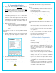
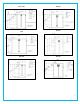
Check the open-circuit voltage (Voc) of every series module using a
digital multimeter (Fluke 170 series are recommended). The
measured system Voc should correspond to the sum of the Vocs of
the individual module. You will find the rated voltage in the technical
specifications of the type of the module used and in the tables at the
end of this Installation Guide. If the measured value is significantly
lower than the expected value, proceed as described under
“Troubleshooting an excessively low voltage”.
Determine the short-circuit current (Isc) of every series circuit. It can
be measured directly by connecting the digital multimeter connected
in the two terminals of series circuit or module, Attention, the rated
scale of the ammeter or the rated current of load should more than
1.25 times than the rated short-circuit current of series module. You
will find the rated current in the technical specifications of the type
of module used. The measured value can vary significantly,
depending on weather conditions, the time of day and shading of
the module.
To identify the commonly low voltage and excessively low voltage, the
commonly how voltage mentioned here is the decrease of open-circuit
voltage of the module, which is caused by the temperature rising of solar
cells or lower irradiance. Excessively low voltage is typically caused by
improper connections at the terminals or defective bypass diodes.
First, check all wiring connections to make sure it is not open-circuit
or is not connection well.
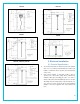
Check the open-circuit voltage of each module:
Fully cover the modules with an opaque material.
Disconnect the wiring at both terminals of the modules.
Remove the opaque material from the module to be checked and
measure the open-circuit voltage at its terminals.
If the measured voltage is only half of the rated, this indicates a
defective bypass diode. Refer to ‘Testing and replacing bypass
diodes’.
In the case of not very low irradiance, if the voltage across the
terminals differs from the rated value by more than 5 percent, this
indicates a bad electrical connection.