
Full Product Manual

4
2. Product Identification
Renogy modules have been qualified for Application Class A.
Modules qualified for safety through IEC 61140 and within this
application class are considered to meet the requirements for Safety
Class II. Modules rated under this class should be used in systems
operating at a voltage above 50 VDC or power above 240 W, where
general contact access is anticipated.
A photovoltaic system composed of UL1703 certified modules
mounted on a UL2703 certified mounting system should be evaluated
in combination with roof coverings in accordance with UL1703
standard, with respect to meeting the same fire classification as the
roof assembly. UL-1703, includes revisions through October 12,
2015, Section 16 and 31.1.2; UL790-2014
Module Fire Performance Type 1
o Mounting systems with a System Fire Class Rating (Class
A, B, or C), tested in conjunction with fire rated “Type 1”
modules, are considered to be acceptable for use by
Renogy.
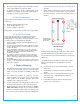
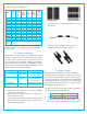
Each module has three labels on its rear side providing the following
information:
Nameplate: describes the product type; rated power, rated current,
rated voltage, open circuit voltage, short circuit current, all as
measured under standard test conditions; weight, dimension etc.
Bar code: each individual module has a unique serial number.
Do not remove any label. If the label is removed the product warranty
will no longer be honored by Renogy.
3. Installation Considerations
Before installing, obtain information about any requirements and pre-
approvals for the site, installation, and inspection from the relevant
authorities.
Check applicable building codes and ensure that the structure can
bear the module system load
Ensure the supporting roof has fire resistant roof covering
Renogy modules are listed as Class C under the UL790 Standard.
3.1 Unpacking and Storing
Unpack module pallets carefully, making sure to follow all directions on the
pallet.
Do not step, walk, stand, or jump on any modules. Localized heavy
loads may cause variances of micro-cracks on the cells which will
ultimately compromise module reliability
Do not carry modules on your head or carry modules through the
wires or junction box
Do not use sharp instruments on the modules, especially the
sensitive backsheet
Do not leave modules unsupported or unsecured
Keep all electrical contacts clean and dry
3.2 Pre-Installation Requirements
Ensure that the modules meet the general technical system
requirements.
Ensure other system components do not damage the modules
mechanically or electrically
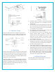
Modules can be wired in series to increase voltage or in parallel to
increase current. Series connections have the modules go from
positive of one module to negative of the second module. Parallel
connections connect the positive cables of one module and the
second module.
Bypass diodes in the modules depends on the model itself.
Modules must not be connected together to create a voltage that is
higher than the maximum system voltage.
A maximum of two strings can be connected in parallel without
needing to incorporate an over-current protection device.
Only modules with similar electrical output should be connected in
the same string to avoid mismatch effects.
The small drainage holes on the undersize of the module must not
be blocked.
Avoid shading—even minor partial shading reduces yields. Sunlight
should be able to reach the module even on the shortest day of the
year. Shading can affect module service life.