
Installation Guide

5
The module should be facing true south in northern latitudes and true
north in southern latitudes for best power production.
For detailed information on the best elevation tilt angle for the
installation, refer to standard solar photovoltaic installation guides or
a reputable solar installer or systems integrator.
3.3 Site Considerations
Renogy modules should be installed in locations that meet the following
requirements:
Operating Temperature within -40°F to 194°F
Relative humidity within 45% to 95%
Avoid trees, buildings, or obstructions
Renogy modules are designed with a mechanical load strength of 2400Pa
3.4 System Fire Rating
The fire rating of Renogy modules is only valid when mounted in the
manner specified in the mechanical mounting instructions. When
installing modules on rooftops, please ensure the assembly is mounted
over a fire resistant roof covering rated for the application.
Renogy non-BIPV modules are certified through Intertek as Type 1
for fire performance
The System Fire Class Rating of the module or panel in a mounting
system combination with a fire resistant roof rating is the only way
to achieve this rating.
Any system limitations on inclination or accessories required to
maintain a specific Fire Class Rating should be clearly specified in
the installation instructions and UL2703 Certification of the
mounting system supplier
The modules are intended for use in general open-air climate, as
defined in IEC 60721-2-1: Classification of environment condition
Part-2-1: environmental conditions appearing in nature temperature
and humidity.
To preserve individual module fire class rating, PV modules must be
mounted on a non-combustible surface standoff height of at least 5
inches with 0° inclinations.
4. Module Mounting
All installation methods herein are only for reference and Renogy will
not provide their own mounting components. Instead, the system
installer is responsible for making sure installation is abided by all
codes.
Any mounting system limitations on inclination or accessories
required to maintain a specific System Fire Class Rating should be
clearly specified in the installation instructions and UL2703
certification of the mounting system supplier.
In order to maintain the fire class rating, the distance between the PV
modules (front glass) and the roof surface should be at least 5 in.
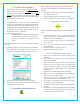
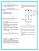
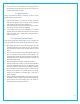
Module mounting must use the pre-drilled mounting holes (Length *
Width: 14mm x 9mm) in the frame. The most common mounting is
achieved by mounting the module using the four symmetry points
close to the inner side on module frame. Refer to the following picture
for more details. Note that the holes in the center (blue) are for
grounding.
Modules should be safely fixed to bear all expected loads, including
wind and snow loads. A minimum clearance of 0.25 in (6.5mm) or
more between modules is required to allow for thermal expansion of
the frames.
RNG100D Example
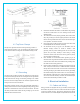
4.1 Bolting
Modules must be mounted using the mounting holes located on the rear
side of the long frame parts using M6 or M8 bolt stainless steel bolts,
nuts, and washers. Refer to the racking manufacturer for specific torque
requirements.
The mounting design must be certified by a registered professional
engineer and comply with local code requirements from relevant
authorities.
Use appropriate corrosion-proof fastening materials—should be
stainless steel
Do NOT drill holes or modify the module frame as it will void
warranty.
Each module must be securely fastened at a minimum of 4 points
on two opposite sides. *Actual bolt depends on railing and
professional installer.
Design load and safety factors will be determined by racking
suppliers or professional engineers.
Mounting Holes
(Length * Width):
14mm x 9mm