ROVER SERIES Maximum Power Point Tracking Solar Charge Controller Rover 60A Version 1.
Important Safety Instructions Please save these instructions. This manual contains important safety, installation, and operating instructions for the charge controller. The following symbols are used throughout the manual to indicate potentially dangerous conditions or important safety information. WARNING CAUTION NOTE Indicates a potentially dangerous condition.
Battery Safety Use only sealed lead-acid, flooded, gel or lithium batteries which must be deep cycle. Explosive battery gases may be present while charging. Be certain there is enough ventilation to release the gases. Be careful when working with large lead acid batteries. Wear eye protection and have fresh water available in case there is contact with the battery acid. Carefully read battery manuals before operation. Do NOT let the positive (+) and negative (-) terminals of the battery touch each other.
Table of Contents 03 General Information 04 Additional Components 08 Optional Components 08 Identification of Parts 09 Installation 10 Operation 19 LED Indicators 27 Rover Protections 29 System Status Troubleshooting 30 Maintenance 30 Fusing 31 Technical Specifications 31 Electrical Parameters 31 General 32 Battery Charging Parameters 32 PV Power – Conversion Efficiency Curves 33 Dimensions 34
General Information The Rover Series charge controllers are intelligent controllers suitable for various off-grid solar applications. It protects the battery from being over-charged by the solar modules and over-discharged by the loads. The controller features a smart tracking algorithm that maximizes the energy from the solar PV module(s) and charge the battery. At the same time, the low voltage disconnect function (LVD) will prevent the battery from over discharging.
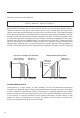
Therefore, assuming 100% efficiency: Power In = Power Out Volts In * Amps In = Volts out * Amps out Although MPPT controllers are not 100% efficient, they are very close at about 92-95% efficient. Therefore, when the user has a solar system whose Vmp is greater than the battery bank voltage, then that potential difference is proportional to the current boost.
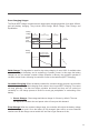
Four Charging Stages The Rover MPPT charge controller has a 4-stage battery charging algorithm for a rapid, efficient, and safe battery charging. They include: Bulk Charge, Boost Charge, Float Charge, and Equalization. A Bulk Charge B Constant charging C Float Charge Boost lk Equalize Boost Bu Battery Voltage Float Recharge Time Battery Current Duration Time:2h (Range:10-180min) Max Current Cumulative Time:3h Time Bulk Charge: This algorithm is used for day to day charging.
The charge controller will reduce the voltage charge to smaller quantity, while lightly charging the battery. The purpose for this is to offset the power consumption while maintaining a full battery storage capacity. In the event that a load drawn from the battery exceeds the charge current, the controller will no longer be able to maintain the battery to a Float set point and the controller will end the float charge stage and refer back to bulk charging.
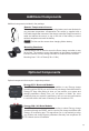
Additional Components Additional components included in the package: Remote Temperature Sensor: This sensor measures the temperature at the battery and uses this data for very accurate temperature compensation.The sensor is supplied with a 9.8ft cable length that connects to the charge controller.Simply connect the cable and adhere the sensor on top or the side of the battery to record ambient temperature around the battery. NOTE Do Not use this sensor when charging lithium battery.
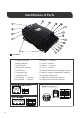
Identification of Parts Key Parts 09 1. Charging Indicator 10. Battery “-” Interface 2. Battery Indicator 11. Load “-” Interface 3. Load Indicator 12. Battery “+” Interface 4. Abnormality Indicator 13. Load “+” Interface 5. LCD Screen 14. External Temperature Sampling Interface 6. Operating Keys 15. Battery Voltage Compensation Interface 7. Installation Hole 16. Controller Parallel Port 8. Solar panel “+” Interface 17. RS232 Communication Interface 9. Solar panel “-” Interface 18.
Installation Recommended tools to have before installation: Screwdriver WARNING WARNING Multi-Meter Connect battery terminal wires to the charge controller FIRST then connect the solar panel(s) to the charge controller. NEVER connect solar panel to charge controller before the battery. Do NOT connect any inverters or battery chargers into the LOAD TERMINAL of the charge controller. INVERTER BATTERY CHARGER HIGH AMP DRAWING DEVICE CAUTION CAUTION Do not over tighten the screw terminals.
Remove Cover Battery 11
Solar Panels Load (optional) 12
Bluetooth Module Communication (optional) Temperature Sensor (optional, not polarity sensitive) Place the sensor close to the battery Install Cover 13
Mounting Recommendations WARNING NEVER install the controller in a sealed enclosure with flooded batteries. Gas can accumulate and there is a risk of explosion. 1. Choose Mounting Location—place the controller on a vertical surface protected from direct sunlight, high temperatures, and water. Make sure there is good ventilation. 2. Check for Clearance—verify that there is sufficient room to run wires, as well as clearance above and below the controller for ventilation.
Using Mounting Holes Step 1. Measure the distance between each mounting hole on the Rover. Using that distance drill 4 screws onto desired surface. Step 2.
Step 3. Verify all screw heads are inside the mounting holes.
Using Mounting Brackets Step 1.
Step 2. Align the mounting brackets to desired surface and use the appropriate screws to drill into surface(screws not included) Step 3.
Operation Rover is very simple to use. Simply connect the batteries, and the controller will automatically determine the battery voltage. The controller comes equipped with an LCD screen and 4 buttons to maneuver though the menus. Main Display Main menu Real-time monitoring Load mode Parameters setting 485:communication Statistic data Historical data of the current day Device information ROVER 60 NOTE 19 ROVER 60 The Battery Capacity (SOC%) is an estimation based on the charging voltage.
Page Up/ Increase parameter value /+ /- Page Down/ Decrease parameter value Return to the previous menu Main Menu Battery icon and SOC Load current icon Charging current icon Day or night indicating icon Load icon and state indication 37% Solar panel voltage charging power 26.8V 0W charging current 11.
Icon or Value State Description Steady on Nighttime Steady on Daytime Steady on A dynamic arrow indicates charging is in progress. 0-100% Current battery capacity 0% Slow Flashing Battery over-discharged 100% Flash Flashing Battery over-voltage Steady on Load Terminal in on Steady on Load Terminal is off Fast Flashing Overload or short-circuit protection Real-Time Monitoring To view this screen in the main menu, tap the Right arrow button.
Screen 1 2 3 4 Displayed Item/Parameter Description Chag State: Idle Charging State Indicators: “Idle”, no charging “MPPT”, MPPT charging “EQU”, Equalization charging “BST”, Boost charging “FLT”, Float charging “LIMIT”, current-limited charging BatVol: 11.
Programming Load Terminal Load mode setting icon LOAD OFF Load state Manual Load mode 1. If the characters displayed on top of "" are "ON", it indicates that the load is switched on 2. Tap " Right Arrow Button" to enter the load setting mode, and right below the "", the mode characters or digits will begin to flash.
Parameter Settings System voltage indication Battery type indication Setting icon AUTO/SLD SET BST:14.4V LVD:11.0V Boost charging voltage 14.4V Over-discharge voltage 11.0V To enter the following settings, in the parameters setting screen press the Right arrow button.
28DAYS Statistical Data Statistics icon TOTAL ANALYSI DAYS: LVDC: 9 5 Number of operating days: 9 Number of over-discharges:5 To enter the following settings, in the Statistical Data screen press the Right arrow button.
Screen 1 2 3 4 Displayed Parameter Description xxxx Days Ago xxxx: select the historical data of day xxxx (counting backwards) 0000: current day 0001: yesterday 0002: the day before yesterday MinBatVol: 11.5V The selected day’s min. battery voltage MaxBatVol: 11.6V The selected day’s max. battery voltage MaxChgCrt: 0A The selected day’s max. charging current MaxLodCrt: 0A The selected day’s max. discharge current MaxChgPow: 0W The selected day’s max.
Screen 1 Displayed Parameter Description Model: ROVER60 Controller model HW-ver: 00.02.07 Hardware version SW-ver: 00.00.04 Software version Serial: 123456789 Controller serial number LED Indicators ①---PV array indicator Indicating the controller's current charging mode. ②---BAT indicator Indicating the battery's current state. ③---LOAD indicator Indicating the loads' On/ Off state. ④---ERROR indicator Indicating whether the controller is functioning normally.
PV Indicator (1) Status WhiteSolid The PV system is charging the battery bank White Slow Flashing The Controller is undergoing boost stage White Single Flashing The Controller is undergoing float stage White Fast Flashing The Controller is undergoing equalization stage White Double Flashing The oversized PV system is charging the battery bank at the rated current. Off The PV system is not charging the battery bank. PV not detected.
Rover Protections Protection 29 Behavior PV Array Short Circuit When PV short circuit occurs, the controller will stop charging. Clear it to resume normal operation. PV Overcurrent The controller will limit the battery charging current to the maximum battery current rating. Therefore, an over-sized solar array will not operate at peak power. Load Overload If the current exceeds the maximum load current rating of 21A, the controller will disconnect the load.
System Status Troubleshooting PV indicator Off during daylight BATT Indicator Troubleshoot Ensure that the PV wires are correctly and tightly secured inside the charge controller PV terminals. Use a multi-meter to make sure the poles are correctly connected to the charge controller. Troubleshoot White Slow Flashing Disconnect loads, if any, and let the PV modules charge the battery bank. Use a multi-meter to frequently check on any change in battery voltage to see if condition improves.
Fusing Fusing is a recommended in PV systems to provide a safety measure for connections going from panel to controller and controller to battery. Remember to always use the recommended wire gauge size based on the PV system and the controller. NEC Maximum Current for different Copper Wire Sizes AWG 16 14 12 10 8 6 4 2 0 Max. 18A 25A 30A 40A 55A 75A 95A 130A 170A Current The NEC code requires the overcurrent protection shall not exceed 15A for 14AWG, 20A for 12 AWG, and 30A for 10AWG copper wire.
General RVR60 Model 285 x 205 x 102mm (11.2 x 8.1 x 4.0in) Dimensions Mounting Holes 4 x Ø10mm Max Terminal Size Net Weight Working Temperature Humidity Range Enclosure Altitude Communication 25mm2 4 AWG 3.6 kg 7.9 lbs -35°C to +45°C ≤ 95% (NC) IP32 < 3000m RS232 RS485 Certifications ETL Listed to UL1741 Battery Charging Parameters Battery GEL SEALED FLOODED LI (LFP) USER 16 V 16 V 16 V 16 V 9-17 V ----- 14.6 V 14.8V ----- 9-17 V Boost Voltage 14.2 V 14.4 V 14.6 V 14.
1. Default charging parameters in LI mode are programmed for 12.8V LFP battery. Before using Rover to charge other lithium battery, set the charging parameters according to the suggestions from battery manufacturer. 2. The above parameters are based on 12V system settings. Parameters are multiplied by 2 for 24V systems, multiplied by 3 for 36V systems, and multiplied by 4 for 48V systems. 3. For Equalization Interval Setting under USER mode, 0 Day refers to turning off the equalization function.
Dimensions 205 mm (8.07 in) RVR60 102mm (4.01in) 285mm (11.22 in) 102mm (4.01in) 34mm (1.03in) 170 2.5mm (0.09in) NOTE Dimensions in millimeters (mm) RVR60 with mounting brackets 109.2mm (4.29in) 30.5mm (1.02in) 285mm (8.55in) 178mm(7.0in) 109.2mm (4.29in) 218mm (8.58in) 227mm (8.93in) 170mm (6.69in) Ø4.5 4xØ10 180mm (7.08in) 8xØ11.8 2.5mm (0.
RENOGY.COM Renogy reserves the right to change the contents of this manual without notice. US 2775 E Philadelphia St, Ontario, CA 91761, USA 909-287-7111 www.renogy.com support@renogy.com CN 苏州高新区科技城培源路1号5号楼-4 JP https://www.renogy.jp supportjp@renogy.com CA https://ca.renogy.com supportca@renogy.com AU https://au.renogy.com supportau@renogy.com UK https://uk.renogy.com supportuk@renogy.com DE https://de.renogy.com supportde@renogy.com 400-6636-695 https://www.renogy.cn support@renogy.