
Owners manual

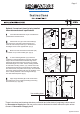

Fasten conversion panel (E). Place cover plate (F) on top of
conversion panel (E) and secure with cover plate screws (T4). (Fig 5)
Slide the medium decorative nut (H) followed by the plastic
slip joint washer (Z5) to the bottom end of the 47" stainless steel tube and
loosely attach to the receiving thread of the conversion panel (E). (Fig 5)
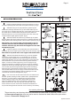
Install the nipple (P) to the water fitting from the wall. Slide in
the flange (Q) onto the nipple (P) and install the shut off valve (N). (Fig 7)
Turn on the shut off valve and fill the tank to its waterline and
test flush system,checking for leaks. (Water level is preadjusted from
the factory; in some instance re-adjustment might be necessary.
Caution: Before turning on the water, please make sure that all
parts are installed properly. Never use abrasives, detergents or
acids to clean the unit. Use only mild soap and water with a soft
cloth to clean the set, the use of harsh chemicals and abrasives of
any kind will damage the set which will not be covered by the warranty.
Note: Steps 6 & 7 involves slight pulls and pushes of the 47"
stainless steel tube th
at will enable proper fitting of the 47"
stainless steel tube (G), then
check final alignment of the tube
and tighten all joints.
Note: Please wrap both sides of the nipples with thread sealer.
Slide brass slip joint nut (Z6) followed by plastic slip joint
washer (Z5) and large decorative nut (J) with rubber washer (K) into
top end of the 47" stainless steel tube (G), Insert rubber water restrictor
(Z7) inside the 47" stainless steel tube (G) and loosely attach the
large decorative nut (J) to the receiving thread of the flush valve (A2)
on the woodtank slightly tighten all joints. (Fig 6)
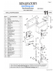
47" Tube (G)
47" Tube (G)
These instructions and drawings disclose confidential and other data of proprietary nature owned
by Renovator’s Supply Inc. and may not be used or disclosed to others without the prior written
consent of Renovator’s Supply Inc.©
www.rensup.com
Your existing toilet bowl
ZpipeConv072010
Slide the small brass decorative nut (V) from the opposite
end of the 1/2" water supply line (L) (noncollared end), and insert
cone washer (W) in between the 1/2" water supply line (L) and the
small brass decorative nut (V) on the collared end. Connect the small
brass decorative nut (V) to the fill valve receiving thread and hand
tighten, connect 1/2" water supply line (L) and 12" supply line (O)
using the compression coupling (M), then remove the nut and brass
sleeve from the shut off valve (N), align the 12" supply line (O) to the
shut off valve (N) measure appropriate length and trim accordingly.
Slide the brass nut followed by the brass sleeve removed from the
shut off valve earlier onto the 12" supply a wrench and make sure all
connections are squarely aligned to assure no leakage. Do a final
check that all connections are tightened. (Fig 8)
Page 4