PV Grid-connected Inverter Digiwatts RN3000US Installation Guide Copyright © Renovo Power Systems. All rights reserved. (Rev 1.
Reproduction and storage in a retrieval system, or transmittal, even partially, of the contents of this manual is strictly forbidden without prior authorization of Renovo Power Systems. All such warranties are expressly disclaimed. Neither Renovo Power Systems nor its distributors or dealers shall be liable for any indirect, incidental, or consequential damages under any circumstance.
IMPORTANT SAFETY INSTRUCTIONS SAVE THESE INSTRUCTIONS This manual contains important instructions for Model RN3000US SOLAR INVERTERS. It must be accurately understood and followed during installation and maintenance of the inverter. The Digiwatts system is designed according to international safety standards, however with all electrical and electronic equipment, installation and operation must follow some preventive measures.
In addition to the safety and hazard symbols described on the previous pages, the following symbols are also used in this Installation Guide. Make sure to read the labels and fully understand them before installing the equipment. INFORMATION This symbol calls attention to supplementary information that you should know and to ensure optimal operation of the unit. Markings on this product The following symbols are used as markings on this product with the following meanings.
General Warnings All electrical installations must be done in accordance with the local and National Electrical Code ANSI/NFPA70. For installation in Canada the installations must be done in accordance with applicable Canadian standards. The Digiwatts unit contains no user-serviceable parts. For all repair and maintenance always return the unit to an authorized Renovo Power Service Center.
Table of Contents 1 Introduction........................................................................................................... 7 1.1 Validity....................................................................................................... 7 1.2 Target Group .............................................................................................. 7 1.3 Product Overview .................................................................................... 8 1.4 Feature Overview..........
5.5 Communication Wiring ............................................................................... 39 5.5.1 RS485 Communication .................................................................... 39 5.5.2 Network communication.............................................................. 41 5.6 Closing the Digiwatts unit............................................................................ 41 6 Commissioning .......................................................................................
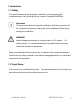
1 Introduction 1.1 Validity This manual describes the assembly, installation, commissioning and troubleshooting of the following Renovo inverter: Digiwatts RN3000US. Information To help avoid problems during the installation, familiarize yourself with the installation process by reading the entire Installation Guide before starting the installation. WARNING! Lethal voltages are present at various points in a PV system.
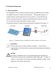
1.3 Product Overview Basic information The Digiwatts inverter is used to convert DC power generated by the PV arrays into stable AC power for output to the utility grid. The Digiwatts system is a transformerless inverter and performs this conversion in a very efficient way, without moving components, using only solid state power electronic devices. It is a crucial unit in the small-scale PV power system. An example of basic PV power system components is shown in the Figure 1-1.
Electrical block diagram Figure 1-2 shows the main circuit of Digiwatts transformerless grid-connected inverter system. A boost circuit raises input DC voltage within the inverter. Then a Maximum Power Point (MPP) tracker ensures that maximum power is extracted from the PV arrays. Afterwards, a full bridge inverter circuit converts DC power to AC power which is then output from the unit.
Terminals of the Digiwatts system 4 5 1 6 2 7 3 8 Figure 1-3 Terminals Description Table 1-1 Terminals Description Item 1 2 3 4 5 6 7 8 Name DC input DC input Network terminal LCD screen Switch AC output AC output RS485 terminal Installation Guide Description Input port for 1/2 inch conduit Input port for 3/4 inch conduit Standard network interface - CAT5/RJ45 Running data is displayed on the LCD screen Disconnect inverter from PV array and power grid Output port for 1/2 inch conduit Output port
Dimensions and weight Figure 1-4 Dimensions of the Digiwatts unit Table 1-2 Dimensions and weight Type RN3000US Depth Width Height Weight (mm/Inch) (mm/Inch) (mm/Inch) (kg/lb.) 195/ 7.7 459 / 18.1 490 / 19.
1.4 Feature Overview The Digiwatts system represents state-of-the-art technology. Several key features: High reliability and safety High efficiency Simple installation Quiet operation LCD Display Powder coated die-cast enclosure Operating Temperature The Digiwatts system has been equipped with a passive radiator used to maintain full power output at ambient temperatures as high as 60°C.
lagging reactive current into the utility grid. This method has been proven by independent test labs to effectively destabilize and disconnect from a balanced island condition. PV Insulation Fault Detection Before the inverter connects to the grid, the Digiwatts system will detect the isolation of PV+ and PV- to the ground. When the insulate impedance is less than 1MΩ, the inverter will not function. After the inverter is connected to the grid, the system will detect the residual current.
1.5.2 Safety Instructions DANGER Danger to life due to high voltages in the inverter! All work on the inverter may only be carried out by qualified personnel. The appliance is not to be used by children or persons with reduced physical, sensory or mental capabilities, or lack of experience and knowledge, unless they have been given supervision or instruction. Children should be supervised to ensure that they do not play with the appliance.
When the photovoltaic array is exposed to light, it supplies a DC voltage to this equipment. WARNING For continued protection against fire, replace fuses only with units of same type and ratings. CAUTION Risk of electric shock form energy stored in capacitor! Do not remove cover until 15 minutes after disconnecting all sources of supply. CAUTION The Digiwatts system shall not be connected to a battery due to lack of over- current protection provided in the unit.
1.5.3 Symbols on the Type Label Table1-3 Symbols on the Type Label Icon Explanation The product works with high voltages. All work on the product may only be done as described in the documentation. The product can generate heat during operation. Avoid coming into contact with the product during operation. Read the product’s documentation before working on it. Follow all safety precautions and instructions as described in the documentation. The inverter can be installed outdoors.
1.6 Installation Overview This section provides an overview of the installation process and User Manual contents. Section 1: Unpacking and Inspection Provides instructions for unpacking and inspecting the Digiwatts system for shipping damage. Section 2: General Use Read this manual carefully before using this product. If you encounter any problem during installing or running this unit, please check this manual first before contacting your local dealer or representative.
Section 8: Technical Specifications Provides functional technical data plus connection diagrams and torque specifications for the connection of cables and fasteners of the Digiwatts unit. 2 Unpacking and Inspection NOTICE! The distributor delivered your Digiwatts unit to the carrier fully functional and securely packaged. Upon acceptance of the package, the carrier assumes responsibility for its safe delivery.
WARNING! The Digiwatts unit weighs up to 27kg. To avoid injury, be sure to use proper lifting techniques and secure the help of someone to assist in the unpacking and installation of the inverter. If you need assistance with a damaged Digiwatts unit, contact Renovo Power. Contact information for Renovo Power Systems is provided below. North America: Renovo Power Systems LLC 2723 South State St., Suite 150 Ann Arbor, MI 48104 Tel: 855-RENOVO1 (736-6861) Fax: 888-810-6454 http://www.renovo-usa.
2.1 Scope of Delivery Table 2-1 Delivery Contents Item A B C D E F Qty.
3 AC Voltage Configuration The Digiwatts system is compatible with 240V AC output. The Digiwatts unit comes from the factory pre-configured for utility interconnection at 240V AC. Figure 3-1: Common Utility Voltage Configurations Information When using 240 V Delta Corner grounded grids, connect the N terminal to the grounded corner.
WARNING! The Digiwatts unit weighs up to 27 kg. To avoid injury, be sure to use proper lifting techniques and secure the help of someone to assist in the unpacking and installation of the inverter. Information It is required that the inverter be mounted so that the rating label on the side of the inverter is visible. 4.1 Choosing a Mounting Location Consider the following guidelines, cautions, and warnings when choosing a mounting location for the Digiwatts unit.
children. The Digiwatts unit emits a slight vibrating noise when operating. This vibration is normal and has no effect on performance, but it can be objectionable if the inverter is mounted on a wall in a living area, on the outside of a wall that is near a living area, or on certain types of materials, such as thin wood paneling or sheet metal. Install the Digiwatts unit in a location that maintains an ambient air temperature less than 60°C to maintain a safe internal component temperature.
must be mounted with a clearance of at least 50cm at all points, but 100cm bottom side. Figure 4-2 the outer dimensions of the Digiwatts unit Information You must ensure that there is sufficient clearance for the flow of the air around the Digiwatts unit! In a normal operating environment with good ventilation, 50 cm of clearance is sufficient. The National Electrical Code may require increased working clearances. 4.3 Mounting Procedure 4.3.
the wall is plumb. Be sure to use the appropriate type of mounting hardware for the wall material. 4.3.1.
1 2 3 4 5 6 Figure 4-4 Fasten the Bracket against Masonry Wall with Expansion Screws Table 4-1 Mounting Items Item 1 2 3 4 5 6 Description Masonry wall Expansion cylinder Bracket Washer Spring washer Hexagonal nut Mounting the expansion screws: Three fasteners are required to secure the wall mounting bracket to a wall: Two Installation Guide RN3000US Jan13 26
fasteners along the top of bracket using the center holes on each side (centerline spacing of 180mm) and a third fastener at the centerline of the bottom of the bracket (Expansion screws are provided however it is installer’s responsibility to ensure fasteners to bw appropriate for wall material.) Ensure that all fasteners are well secured. 4.3.1.
Two fasteners are required to secure each of the cross bar to a stud wall. The fasteners must be fastened on the wood stud of the wall. Fastener holes of cross bars must be aligned on vertical direction. The vertical distance between cross bars is 210mm. (Wood screws are provided however it is installer’s responsibility to ensure fasteners to be appropriate for wall material.) Mounting the bracket to the cross bars Six M6 machine screws are required to secure the bracket to the cross bars.
Table 4-2 Mounting Items Item 1 2 3 4 5 6 Description Stud wall Cross Bars Bracket M6 washer M6 spring washer MS machine screw 4.3.2 Mounting the Digiwatts Unit to the Bracket Use the following procedure to mount the Digiwatts unit once wall bracket is secured to the wall. 1) Carefully hook the slots on the rear of the Digiwatts case onto corresponding vertical tabs of the wall bracket. Figure 4-8 Mounting the Inverter to Bracket WARNING! The Digiwatts unit weighs up to 27 kg.
Lock (optional) M6 machine screw Figure 4-9 Affix Bottom Tabs of Digiwatts unit to Mounting Bracket 3) Inspect the Digiwatts unit from both sides to ensure that it sits centered on the wall screws. 4) Carefully verify that the Digiwatts unit is mounted firmly in place. 5 Wiring the Digiwatts unit This section provides step-by-step procedures and other information required for wiring the Digiwatts unit to the PV array and the utility grid.
section. Deviating from these procedures could expose you to lethal voltage. WARNING! Always turn OFF all switches in the PV system before connecting any wires to or disconnecting any wires from the Digiwatts unit. Information The DC input and AC output circuits are isolated from the enclosure and system grounding, as required by section 250 of the National Electric Code, ANSI/NFPA 70.
5.1 Sequence of Connecting Figure 5-1 Electrical Connection Diagram 1) De-energize all energy sources by opening all AC and DC disconnects and/or breakers. 2) Wire from AC breaker to the Digiwatts unit. 3) Wire from the PV DC breaker to the Digiwatts unit . 4) Turn the DC switches and/or breakers ON. 5) Turn the AC switches and/or breakers ON. 6) To disconnect the Digiwatts unit, first turn OFF all AC breakers and then all DC breakers. The AC system should always be disconnected before the DC system.
5.2 Opening the Digiwatts ON ON OFF OFF Figure 5-2 (a) Turn the switch to off position Figure 5-2 (b) Opening the Digiwatts unit 1) Turn the switch to OFF position. 2) Remove the four machine screws and lock washers from the disconnect housing cover. 3) Open the cover smoothly.
grounded properly and is fully sealed to the case. Handle the cover carefully, as even seemingly minor damage to the cover could result in an inadequate seal between the cover and the case, thus allowing moisture to enter the case and damage the sensitive electronic components. NOTICE! Do not install the Digiwatts unit during periods of precipitation or high humidity (>95%). Moisture trapped within the enclosure may cause corrosion and damage to the electronic components. 5.
manner in which it is connected to the utility grid. See NEC Section 690-64(b)(2). WARNING! To reduce the risk of fire, connect only to a circuit provided with the required branch circuit over-current device sized in accordance with the National Electric Code, ANSI/NFPA 70. The maximum size over-current device shall not be more than 50 amperes. WARNING! You must connect the wires that carry the AC voltage from the Digiwatts unit to the utility grid in the order described in this procedure.
L1 L2 Ground Figure 5-3 AC Connection Terminals 5.4 Wiring the DC input This subsection provides procedures for wiring the DC input from the PV array to the Digiwatts unit. 5.4.1 DC Connection Requirements WARNING! All electrical installations must be done in accordance with all local electrical codes and with the National Electrical Code (NEC), ANSI/NFPA 70. For installation in Canada the installations must be done in accordance with applicable Canadian standards.
to the Digiwatts. Voltage drop and other considerations may dictate that larger size wires be used. Use only solid or stranded wire but not fine stranded wire. WARNING! The DC disconnect for the inverter must have a minimum rating of 600VDC and 25A continuous. Information Series fusing may be required depending on the type of PV module used in the system. See NEC 690.9.
DC-input voltage that exceeds the maximum DC-input-voltage range will cause irreversible damage to the Digiwatts unit and void the warranty! Always configure the DC-input-voltage range correctly before connecting the DC-input wires from the PV array to the Digiwatts unit. The PV modules connected to Digiwatts unit should be: ---Same type ---Identical alignment ---Identical tilt The maximum length of DC connecting cables should not exceed 30m as required by the EMC Directive.
CAUTION! Avoid using wire nuts to for any connections in the PV system. Wire nuts are a frequent cause of unreliable, resistive connections, and ground faults. 5.4.2 Connecting the DC Wires 1) Verify that the AC breaker(s) are OFF. 2) Verify that the DC breaker is OFF. 3) Pull the DC wires from the DC breaker through the conduit into the interior of the Digiwatts unit. 4) Connect the positive and negative DC wire to the terminal labeled DC+ and DC- in the Digiwatts unit.
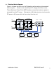
Figure 5-6 Communication Wiring Wiring procedure: 1) A resistance with 120Ω is connected at the initiating terminal of RS485 bus. 2) Plug the connector of the RS485 cable into corresponding RS485 terminal of Inverter 1 3) The two lines of the other end of RS485 cable, labeled A and B, are connected to corresponding lines of RS485 bus, as the above diagram. 4) Connect other inverters to RS485 bus in the same way.
5.5.2 Network communication You can connect inverter to Internet or PC by router (the router is not specified, you can get any brand or model in the market). Wiring procedure: 1) Connect the router to PC and internet. 2) Configure the router via PC. 3) Connect the inverter to router. 5.
sealing of the cover and that no pressure will be exerted on the connections when the cover is replaced. 2) Locate the four machine screws and gland you removed to take the cover off the Digiwatts unit. Make sure you have all four screws and gland, as all of this hardware is necessary to ensure proper grounding and a weather-tight seal. 3) Check the seal on the inside of the cover to ensure it is undamaged and in the correct position.
Observe the operating instructions To commission the Digiwatts unit, follow these instructions: 1) Make sure any covering placed over the PV array is removed. 2) Connect the grid voltage to Digiwatts unit by switching on main AC circuit breaker. 3) Connect the external DC. If there is sufficient sunlight available, the Digiwatts unit will enter the “Wait” mode at this time and the Wait LED will begin to blink.
7 Displays and Messages 7.1 LED Operation Indications Figure 7-1 Front Cover LED Status Indicators Waiting The Wait LED is blinking, the other two are off. The PV energy is sufficient to enable self-checking, but is insufficient for feeding power to the utility grid. Normal Operation The Run LED is on, the other two are off. The inverter has determined that there is enough voltage from the array to operate. The Digiwatts unit adjusts the voltage and current from the PV array to maximize PV output power.
7.2 Status Messages on the LCD Display 7.2.1 Activation of the LCD Backlight The LCD backlight is activated by knocking on the lid. The backlight shuts off automatically after 1 minute. 7.2.2 Switching interface The interface can be switched by knocking on the lid while the backlight is activated. The interface can be switched between Operation Interface and Time-Power Curve Interface. 7.2.
Table 7-1 Operation Interface Descriptions Item Parameter Description 1 Fault Fault messages (only appears if fault condition) 2 Notice 3 Input current PV input current 4 Input voltage PV input voltage 5 Power Power feeding to grid 6 E-Day Energy generated for the day 7 E-Total Total energy generated since installation 8 Output voltage Voltage feeding to grid 9 Output current Current feeding to grid Special status messages (Overheated, low-power operating, etc.
Table 7-2 Time-Power curve interface description Item Parameter Description 1 Y-axis Power feeding to grid 2 Max. power point 3 4 Time-Power curve X-axis Present max. power point ( The first figure is time, the second is power ) A curve represents the variation of power with time Inverter running time of the day 8 Troubleshooting 8.1 General Our quality control program assures that each inverter is manufactured to exact specifications and is thoroughly verified prior to leaving the factory.
Short description of the problem Display message What error code is indicated? AC line voltage DC line voltage Can you reproduce the failure? Has this problem occurred in the past? What were the ambient conditions when the problem occurred? If yes, how? Information Regarding the PV Modules: Manufacturer name and model number of the PV module Output power of the module Open circuit voltage (Voc) of the module Number of modules in each string If it becomes nece
8.2 Error Messages If a fault occurs, the Digiwatts system generates an error message according to the operating mode and the detected fault.
M_Udc_L DC bus voltage is too low M_Uga_H Grid voltage is too high M_Uga_L Grid voltage is too low M_Vin_H Input voltage is too high M_Vin_L Input voltage is too low M_Vin_Vdc Input voltage and DC bus voltage comparison error Faults detected by slave DSP S_ Cmp _Idc DC component comparison error S_ Cmp _Ilost Residual current comparison error S_ Cmp _IpvIN Input current comparison error S_ Cmp _Temp Temperature comparison error S_ Cmp _UdcIN DC bus voltage comparison error S_ Cmp _UpvI
9 Technical Specifications 9.1 Specifications Item A B C D E F G H I J K L M N O P Q Description Maximum input voltage (DC) Input voltage range(DC) Maximum input current(DC) Output power factor rating (AC) Output voltage range(AC) Operating freq. range or single freq.
9.2 Trip Limits / Trip Times Nominal Freq. (Hz) Trip Limit (Hz) 60 Trip Times (s) >60.5 60.45 - 60.55 max. 0.1602 <59.3 59.25 - 59.35 max. 0.1602 Trip Voltages Nominal Voltage (V) Trip Freq. (Hz) Trip Limit 240 Line-to-Neutral (V)* Trip Times(s) 50% 119 - 121 max. 0.1602 88% 210 - 212 max. 2.002 110% 261 - 263 max. 1.002 120% 287 - 289 max. 0.
Note Installation Guide RN3000US Jan13 53