
Installation guide


Installation Guide RN3000US Jan13
9
Electrical block diagram
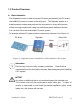
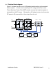
Figure 1-2 shows the main circuit of Digiwatts transformerless grid-connected
inverter system. A boost circuit raises input DC voltage within the inverter.
Then a Maximum Power Point (MPP) tracker ensures that maximum power is
extracted from the PV arrays. Afterwards, a full bridge inverter circuit converts
DC power to AC power which is then output from the unit.
Figure 1-2 Electrical Block Diagram
DSP1 DSP2
Boost
Full bridge
DC+
DC-
L
N
Relay1 Relay2
LCD