
Instructions / Assembly

I-432SC-1214
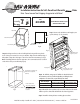
Installation Instructions for Soft-Close Base Filler with Slides
Note: Do not remove front shipping strap prior to installation!
Step 1. Measure scribe rail thickness and length per your
specic cabinetry. (See Fig 1a and 1b)
Step 2. Install upper and lower scribe rails to ller pullouts being careful not to split the
wood. If using screws to attach, be sure to pre-drill rst. Align scribe rails with front edge of
ller pullouts. Align scribe rail to upper section of base cabinet lower mounting. (See Fig 2)
Note: If installing pullout in a frameless application, it is recommended to that a 1/16” thick
scribe rail be used to space the ller unit properly.
Step 3. Pre-drill holes using your 3/16” drill bit. See the table below for
measurements specic to your ller height. After pre-drilling has been
completed on one cabinet side, repeat with adjacent cabinet.
Step 4. Mount ller cabinet pullout to adjacent cabinet. Make sure ller is ush
with the top of the cabinet wall and behind the face-frame if applicable.
Fig 1a
Fig 1b
Cabinet Wall
Scribe rail measurements
Front of Cabinet
Scribe Rail
width dimension
Front of Cabinet
Scribe Rail
Length
Top Scribe Rail is nailed
to edge of top section
Bottom scribe rail is nailed
to edge of bottom section
Fig 2
“Changing the way you think about cabinet organization!”
“Cambiamos su percepción sobre la organización de armarios”
“Nous changeons votre conception de l’aménagement des armoires”
www.rev-a-shelf.com
1-800-626-1126
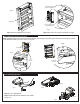
432 Series Filler Pullout Instructions
Instrucciones del armario de relleno deslizante – Serie 432
Directives de montage du module coulissant série 432
I-432-TRI-1012
Fig 1
Step 1. Measure scribe rail thickness and length per your
See Fig 1
Fig 2
Step 2. Install upper and lower scribe rails
or brads. See Fig 2. Note: Align scribe rails
scribe rail to upper section of base cabinet
lower mounting strap or lower section of
wall cabinet lower mounting strap. See
Figs. 3a-b.
Top Scribe Rail is nailed to
bottom edge of top section
Fig 3a
Wall Cabinet
Bottom Scribe Rail is nailed
to edge of bottom section
Top Scribe Rail is
nailed to edge of
top section
Fig 3b
Base Cabinet
Bottom Scribe Rail is
nailed to edge of
bottom section
Fig 4a
Fig 4b
Step 3. (Base Cabinets). Pre-drill 3/16 inch holes 3/8
inch down from top of cabinet and also 27-3/4” down
from top of cabinet. (See Fig 4a-d). Repeat with other
adjacent cabinet.
Fig 5a
Fig 5b
Step 4.
See Fig. 5a-b
Fig 6
Step 5.
to adjacent cabinet 2. See Fig. 6
Fig 8
Fig 9
Step 7. Attach face frame and onlays (not provided) See Fig. 8-9
Fig 7
Step 6. Remove front mounting strap.
See Fig 7.
Filler Cabinet
Base Cabinet
Scribe Rail Meets Face Frame
From inside the adjacent
cabinet screw the 432 to
cabinet top.
Fig 4c Wall Cabinet
Screw 432 to cabinet bottom
from below adjacent cabinet.
Screw 432 to cabinet top
from above adjacent
cabinet.
Fig 4d Base Cabinet
From inside and
above the adjacent
the 432 to cabinet
bottom.
Filler Cabinet
Base Cabinet
Scribe Rail Meets Face Frame
p
Fig 3
TOOLS REQUIRED:
ESTIMATED ASSEMBLY
TIME:
20 MIN
CARE AND MAINTENANCE:
CLEAN WITH A DAMP CLOTH
AND WIPE PARTS DRY
3/16”
Shipping Strap
Step 5. Mount ller cabinet pullout to remaining adjacent cabinet.
12400 Earl Jones Way • Louisville • KY • 40299 | 800.626.1126 • FAX: 502.491.2215 | www.rev-a-shelf.com
Filler Size (Height)
Measurement #1
From Top of Cabinet, Down
Measurement #2
From Top of Cabinet, Down
26” Filler 3/8” 23-7/8”
30” Filler 3/8” 27-7/8”