® Revel I20/I30 In-Wall Loudspeaker Owner’s Manual 3 Oak Park, Bedford, MA, 01730-1413 USA | Telephone: 781-280-0300 | Fax: 781-280-0490 | www.revelspeakers.com Customer Support: Telephone: 781-280-0300 | Sales Fax: 781-280-0495 | Service Fax: 781-280-0499 Please contact Customer Support for information about product shipments. Part No. 351814-002 | Rev A | 03/06 “Revel,” and the Revel logo are registered trademarks of Harman International Industries. U.S.
TABLE OF CONTENTS Documentation Conventions . . . . . . . . . . . . . . . . . . . . . .3 About the I20/I30 . . . . . . . . . . . . . . . . . . . . . . . . . . . . . . .4 Highlights • Product Registration Unpacking . . . . . . . . . . . . . . . . . . . . . . . . . . . . . . . . . . . .5 Loudspeaker Overview . . . . . . . . . . . . . . . . . . . . . . . . . . .7 Driver Complement • Filter Network • Input Panel Installation Considerations . . . . . . . . . . . . . . . . . . . . . .
DOCUMENTATION CONVENTIONS This document contains general safety, installation, and operation instructions for the Revel I20/I30 In-wall Loudspeakers. It is important to read this document before attempting to use this product. Pay particular attention to safety instructions. WARNING Calls attention to a procedure, practice, condition, or the like that, if not correctly performed or adhered to, could result in injury or death.
ABOUT THE I20/I30 Thank you for purchasing the Revel I20/I30 in-wall Loudspeaker. Designed for discerning audiophiles, the I20 and I30 offer versatile, easily integrated in-wall loudspeakers that provide the superior, uncolored sound that is the hallmark of Revel loudspeakers. The I20 and I30 reproduce realistic, accurate signals with minimal coloration and distortion, making them perfect complements to Revel Ultima or Revel Performa front speakers in multichannel setups.
for double-blind listening tests; a laser interferometer for detailed driver analysis; real anechoic chambers for precise tests and measurements; finite element analysis for advanced loudspeaker modeling; and a stereo lithography apparatus for design verification. Adding to the proud lineage of Revel’s Ultima and Performa Series Loudspeakers, the I20/I30 further advances Revel’s reputation as the leading designer and manufacturer of high-quality, high-performance loudspeakers.
Figure 1: Unpacking the I20/I30 2 1 3 Unpacking (continued) To unpack the I20/I30: 1. Place the packing carton in the upright position and fully open the top flaps as shown in step 1 of Figure 1 (above). 6. Invert speaker so it is in the upright position. 7. When the I20/I30 is in the upright position, remove the top pad. 8. Leave the loudspeaker upright in the bottom pad until ready to install. 2.
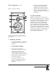
LOUDSPEAKER OVERVIEW DRIVER COMPLEMENT I20/I30 Figure 3: I20 Speaker (Front View) The numbers in Figure 3 (left) correspond with the numbered items in this section. 3 1 4 6 5 2 1. Tweeter • 1-inch (25mm) titanium dome • Under-hung with copper-clad aluminum wire for low distortion • Ferrofluid for high-power handling with reduced compression 2. Woofer The numbers in Figure 3 (above) correspond with the numbered items in the Driver Complement section that begins in the next column. • 7.
Driver Complement (continued) 3. High Frequency Level (dB) Control Provides a shift in the output level of the tweeter or overall high-frequency response (active above approximately 2.5kHz). The options are -1dB, 0dB, and +1dB. midrange and tweeter (in the I30). • Select the “high” (up arrow) setting if the speaker is mounted so that the listener is at tweeter level or above. • Select the on axis setting if the listener position is located directly on axis with the tweeter level.
Driver Complement (continued) Figure 4: I30 Speaker (Front View) 1 3 4 6 5 7 2 • Copper cap stabilizes inductance and controls flux modulation, dramatically reducing distortion. • Optimized and shielded magnetic circuits to minimize harmonic distortion and prevent video monitor interference FILTER NETWORK Optimizes loudspeaker on and off-axis response with a high-order filter at 2.
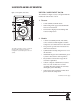
INPUT PANEL Number 1 in Figure 5 (below) corresponds with the numbered item below. 1. Input Connectors Provide input connections from the associated power amplifier/receiver(s). One positive (+) and one negative (-) gold-plated binding post is available. Refer to the Making Connections section that begins on page 16 for additional information. INSTALLATION CONSIDERATIONS Loudspeaker fidelity depends on the following three factors: 1. Loudspeaker accuracy Figure 5: Rear of I20/I30 2.
Installation Considerations (continued) LOUDSPEAKER PLACEMENT The I20 and I30 are designed to offer excellent performance in any listening room or home theater system. Abide by the following placement suggestions for optimal results. 2-Channel or Front Left and Front Right in a Home Theater System The bulleted items that begin below indicate important loudspeaker placement considerations for 2-channel or front left and right installations.
Loudspeaker Placement (continued) Figure 8: Surround Channels with Rear Speakers Front Right Front Left TV • Phillips head screwdriver • measuring tape • utility knife • carpenter’s level • flat blade screwdriver • stud finder To install the I20/I30: Left Side Right Side Couch Left Rear • Right Rear The rear speakers should be placed along the rear wall facing the front of the room. Each rear speaker should be about one-third of the way into the room as shown in Figure 8 (above).
Installation Instructions Figure 11: Ideal Height of Woofer (continued) A C B Note • • • The height of the woofer within the stud bay relative to the entire height of the bay is critical because of standing waves within the cavity. Before installation, determine the height of the cavity. (There might be a fire block that makes it shorter than the entire height from the floor to the ceiling).
Installation Instructions (continued) Figure 13: Clamp Closeup CLAMP Figure 12: Remove Baffle from Mounting Frame Baffle Note how the clamp springs open Figure 14: Clamp Mechanism A Insert frame into wall opening Screw Mounting Frame 3a. (Optional) It is recommended that the frame be painted before it is mounted. For instructions on painting the frame and grille, refer to page 19. Clamp Wall B 4.
Installation Instructions (continued) Figure 15: Frame Alignment Tool the mounting frame so it is level and centered in the cutout. 9. Perform a final torque sequence. Hand-tighten frame screws and check each screw at least twice to make sure they are fully tightened to prevent rattles. Mounting Frame Clamp 10. Remove the Frame Alignment Tool. Frame Alignment Tool 7. Insert the Frame Alignment tool horizontally into the center of the frame.
Installation Instructions (continued) Figure 17: Tighten Allen screws with Allen key wrench Before making connections, note the following: • Make all connections observing the proper polarity, positive-to-positive (+) and negative-to-negative (–). Connections that do not observe the proper polarity will cause poor stereo imaging and diminished bass response. • Use high-quality loudspeaker cable with a maximum total loop resistance of 0.07ohms or less (for each wire run).
Figure 18: Making Connections Terminal Connectors Insert Banana Plug here if desired Binding Post - + Exposed Binding Post (connector removed) Insert Speaker Wire Making Connections (continued) ers' positive (+) and negative (-) binding posts until the holes in their threaded posts are visible. Note High loop resistances that exceed 0.07ohms (for each wire run) will cause the filter network to mis-terminate, resulting in considerable degradation of sound quality.
Making Connections (continued) An alternative connection method, instead of those described in steps 1 to 3, is to attach standard banana plugs to the speaker wires and plug them into the ends of the speaker connectors. See Figure 18 (previous page). OPTIMIZING PERFORMANCE It is highly recommended to make front panel control adjustments before installing the grille. Experiment with settings and carefully listen to ensure that the proper adjustments have been made. 2.
Optimizing Performance (continued) 5. Listen from the primary listening position, increasing volume to a comfortable level. 6. Adjust the High Frequency Level control on each I20/I30 to change high-frequency balance and timbre. 7. Adjust the Listener Axis control depending on the position of the primary listening location. Refer to Figure 19 (previous page). Painting the Frame Proper surface preparation is critical for best results. Use spray, roller (smooth), or a pad to apply the paint.
Painting the Grille (continued) Caution The grille must be painted before it is attached to the frame. To paint the grille: After the paint is dried, install the replacement scrim cloth if desired. To attach the replacement scrim cloth: 1. Place the grille face down on a soft surface. 2. If paint thinner was used to remove scrim remnants, apply a light coating of a spray adhesive to the inside grille surface. Avoid spraying adhesive onto the felt strips.
Grille Removal CAUTION To remove the grille: 1. Insert the small end of the included 1/16-inch allen key into one of the metal mesh holes in the top corner of the grille as shown in Figure 20 (below). 2. With the end of the allen key in the grille hole approximately 1/8-inch, with thumb and forefinger close to the grille, pull up on the allen key to wedge it into the grille hole. 3. Gently pull the allen key to partially pop out the corner of the grille. 4. Repeat steps 1 to 3 for the other top corner. 5.
SPECIFICATIONS Specification I20 I30 Woofer 7.5-inch (190.5mm) 9-inch (228.6mm) Midrange N/A 3.5-inch (88.9mm) Tweeter 1-inch (25.4mm) 1-inch (25.4mm) 40Hz - 20kHz 32Hz - 20kHz 87dB 89dB 15 to 150 Watts 15 to 200 Watts Nominal Impedance 8 Ohms 8 Ohms Crossover Frequency 2.8kHz 300Hz 24dB/octave 2kHz System Frequency Response (±3dB) Sensitivity Recommended Amplifier Power Range 24dB/octave Width 11.811-inches (300mm) 13.583-inches (345mm) Height 16.063-inches (408mm) 20.
OBTAINING SERVICE Before returning a product for warranty or non-warranty service, contact Harman Specialty Group Customer Support to determine the extent of the problem and to obtain a Return Material Authorization (RMA) number. No products will be accepted without an RMA number issued from Harman Specialty Group.
NOTES 24 REVEL I20/I30 In-wall Owner’s Manual
NOTES REVEL I20/I30 In-wall Owner’s Manual 25
Index D 2-channel installations, 11 5-channel installations, 11 A inverted speaker, 13 L Depth, 22 Distortion, Reducing, 4, 5, 7 Listener Axis, 4, 5, 8, 18, 19 Documentation Conventions, 3 Listening Room, 18 Highlights,5 Dome. See Cones.
P U Packing Carton, 5, 6, 23 UL listed, 16 Packing Materials, 6 Unpacking, 5, 6 paint mask, 6 V Painting the Frame, 19 Painting the Grille, 19 Polarity, 16 Voice Coil, 4, 5, 7 Volume Levels, 19 Primary Listening Position, 19 Product Registration, 5 R Rear Speakers, 12 Removing the Grille, 21 Rough-in Bracket, 5, 12 W Wall Cutout Height, 22 Wall Cutout Width, 22 wall openings, 13 wall studs, 12 wall template, 12 Warning, 3 S Warranty, 5, 23 Sensitivity, 22 website, 23 Shipping, 5, 23 Width,
3 Oak Park, Bedford, MA, 01730-1413 USA | Telephone: 781-280-0300 | Fax: 781-280-0490 | www.revelspeakers.com Customer Support: Telephone: 781-280-0300 | Sales Fax: 781-280-0495 | Service Fax: 781-280-0499 Please contact Customer Support for information about product shipments. Part No.