Operator manual REX-***R(F) REX-***R(F) Owner’s Manual Rev. 3 , 2007. THIS PRODUCT IS FOR MEDICAL INSTRUMENT Head Office: 1644-1 Dongwha-Ri Moonmak-Eup Wonju-Si Kangwon-Do, Korea. Tel: 82-1577-8522, Fax: 82-2-840-9569 Homepage: http://www.listem.co.
Operator manual REX-***R(F) Revision History Revision Date Contents 0 April 24, 2003 First release 1 December 29, 2003 Second release 2 April 1, 2004 Third release 3 July 10, 2007 Fourth release LISTEM Corporation 2/90
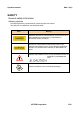
Operator manual REX-***R(F) SAFETY General safety information Advisory symbols The following advisory symbols will be used throughout this manual. The definition and application are described below. Mark Meaning DANGERS ADVISE OF CONDITIONS OR SITUATIONS THAT IF NOT HEEDED OR AVOIDED WILL CAUSE SERIOUS PERSONAL INJURY OR DEATH. ADVISE OF CONDITIONS OR SITUATIONS THAT IF NOT HEEDED OR AVOIDED COULD CAUSE SERIOUS PERSONAL INJURY, OR CATASTROPHIC DAMAGE OF EQUIPMENT OR DATA.
Operator manual REX-***R(F) Please read owner’s manual carefully. It provides instructions on safety, warnings, cautions, and how to prolong the life of the product. 1. INTRODUCTION Dear User. We welcome you as a user of the REX-***R(F) system manufactured by LISTEM Corporation. This manual will guide you to safe and easy Operations for the equipment. For safe and proper operations of this equipment, carefully read the instructions in this manual before operations.
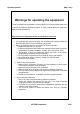
Operator manual REX-***R(F) Warnings for operating the equipment In order to maintain this equipment in good condition for long time, please make sure to operate as following [Important matters in using medical electronic equipment (safety and risk prevention)]. Medical electronic equipment (Safety and protection) Check list 1. It is important that everyone working with X-radiation be properly trained and take adequate steps to insure protection against injury 2.
Operator manual 5. REX-***R(F) After using the equipment, be careful with following. ⑴ Turn off the machine after all the buttons and shuttles are placed in original position. ⑵ Do not force to unplug power cord. ⑶ Be cautious with storage on following. (ⅰ) Do not store in wet place. (ⅱ)Avoid Installation of the equipment where exposed to atmospheric pressure, temperatures, humidity, ventilation, direct sunlight, dust, salt content, sulfur. (ⅲ) Be cautious to keep the equipment steady and level.
Operator manual REX-***R(F) IMPORTANT! X-ray Protection! X-RAY EQUIPMENT IS DANGEROUS TO BOTH PATIENT AND OPERATOR UNLESS MEASURES OF PROTECTION ARE STRICTLY OBSERVED. X-ray equipment if not properly used may cause injury. Accordingly, an operator shall thoroughly read and understand the instructions before attempting to operate this equipment.
Operator manual REX-***R(F) Maximum Permissible Dose (MPD) Many kinds of researches on effects or influences about X-radiation provide basics about maximum permissible dose. These research results were used for ICRP to recommend Maximum Permissible Dose but it is hard to define exactly and it is updated from time to time with new research result.
Operator manual REX-***R(F) A. Radiation protection Because exposure to X-ray radiation may damage health, use great care to provide protection against exposure to the primary beam. Some of the effects of X-ray radiation are cumulative and may be extended over a period of months or years. The beat safety regulation for X-ray operator is "Avoid exposure to the primary beam at all times". The secondary radiation may occur when there is an object on the route of primary beam.
Operator manual REX-***R(F) Protection against electric shock hazard This high frequency X-ray system has been classified as type-B equipment in accordance with IEC-601.1 and IEC-601.2.7 Standards. This classification has been established according to the degree and quality of protection against electric shocks, which is described in terms of the maximum allowable leakage Current. Type-B equipment is suitable for applications involving external or internal contact with the patient, including the heart.
Operator manual REX-***R(F) Users have responsibility for equipment repair and maintenance. Only qualified technician or competent person can operate the equipment. It is dangerous to repair or to inspect inside of the equipment. Please contact an authorized Service Center. It is dangerous to modify or converse the specifications of this equipment.
Operator manual REX-***R(F) Do not use the equipment in the place where combustible gas / explosive gas can be generated. This is not explosion proof equipment. Therefore do not use the equipment in the place where combustible gas / explosive gas may be generated. Don’t spray disinfectant directly to the equipment. Also take extra cautions when using disinfectant spray. If disinfectant is applied inside the equipment, it may cause electric shock or electric leakage.
Operator manual REX-***R(F) Attention! While Operating! (1) It is important that everyone working with X-radiation shall be properly trained (A doctor or a radiotherapist) and takes adequate steps to insure protection against injury. (2) Please contact authorized service center for installation or relocation of the equipment. (3) Please be cautious on following items before using the equipment. ① Check switch, meter operation, high volatage cable, cord, ground wire connection.
Operator manual REX-***R(F) ※ About warranty This equipment is warranted for a 12 month after purchase. Listem has no responsibility in breakdown or damage on following reason. 1. Breakdown or damage caused by installation, relocation or repair by person that is not trained by Listem, Inc. 2. Breakdown or damage that is caused by product not manufactured by Listem, Inc. 3. Breakdown or damage by using other company parts or using inappropriate part to service or repair. 4.
Operator manual REX-***R(F) Abbreviation AEC : Automatic Exposure Control APR : Anatomical Program HU : Heat Unit kV : kilovolt Unit of voltage LED : Light Emitting Diode mA : milli-ampere Unit of tube power mAs : milli ampere second ms(msec) : millisecond: exposure time (minutes) sec : second: exposure time (second) RIS : Radiology Information System HIS : Hospital Information System PACS : Picture Archiving Communication System HSR : High Speed Rotor LISTEM Corporation 15/90
Operator manual REX-***R(F) Table of contents 1. Introduction .............................................................................................................. 17 1.1 Purpose of use 1.2 General features 1.3 Product identification 1.4 Certifications 2. Operating method .................................................................................................... 19 3.1 System configurations 3.2 Operating controls 3.3 Console operating function and exposure parameter 3.
Operator manual REX-***R(F) 1. INTRODUCTION Welcome you as a user of the REX-***R(F) system manufactured by LISTEM Corporation. Dear customer Welcome you as a user of the REX-R/F system manufactured by LISTEM Corporation. This manual will guide you safe and easy use of this equipment. For safe and correct use of this equipment read carefully the instructions in this manual before using the equipment. And keep it at hand for quick reference.
Operator manual REX-***R(F) 1.1 Purpose of use This medical equipment is designed to diagnose human body by providing fluoroscopic or radiographic x-ray image with anatomical structure. 1.2 General features The main features of this equipment are : 1) High frequency inverter type generator. 2) Optimal exposure factors selection as anatomically programmed radiography. 3) Multiple microprocessor control-high reproducibility and linearity.
Operator manual REX-***R(F) 2. OPERATING METHOD This chapter is explains on steps and method of operating method.
Operator manual REX-***R(F) 2. OPERATING METHOD 2.1 System configurations 2.1.1 REX-***R(F) REX-R(F) System covers following model and can be configured following components.
Operator manual REX-***R(F) 2.2 Operating controls 2.2.1 REX-***R AEC On / Density Increase Button AEC Off / Density Decrease Button 1. Power Off Button 13. 2. Power On Button 14. 3. Small Focal Spot Indicator 15. Tube1 Select Button 27. Anatomical View Select Button 4. Large Focal Spot Indicaton 16. No Bucky Select Button 28. Body Region Select Button 5. Over Load Indicator 17. Bucky1 Select Button 29. Escape Select Button 6. Error Indicator 18. Bucky2 Select Button 30.
Operator manual REX-***R(F) 2.2.2 REX-***RF Fluoroscopic console Radiographic console 16 2. Power On Button 17. Bucky1 Select Button 32. Ready Finish Indicator 3. Small Focal Spot Indicator 18. Bucky2 Select Button 33. X-ray Indicator 19. Tube1 Select Button 34. Preparation Button 5. Over Load Indicator 20. Time/mAs Select Button 35. Exposure Button 6. Error Indicator 21. Function1 Button(Spare1 Button) 36. Magnification Select Button 7. KV Increase Button 22.
Operator manual REX-***R(F) 2.2.3 System power ON/OFF 1) Power ON Turn ON the generator by pressing this button. The green lamp will come on and the screen shown on the left will appear displayed "Initializing..." 2) Power OFF Turn OFF the Generator by pressing this button. 2.3 Console operating function and exposure parameter 2.3.1 Power ON/OFF ON : Turning on the power by pressing the button and starting the generator. The power for the x-ray sysytem will come on standby.
Operator manual REX-***R(F) BUCKY 1 - Selecting Bucky 1 by pressing this button. - If the thickness of a subject become thick, it causes loss of the image due to the effect of the scattering line from the subject. Therefore, when you take X-ray, you should select BUCKY 1 to prevent image quality from contrast loss by scattering line. - You should use this button when you take X-ray a subject on the table and should take X-ray after inserting a cassette into the cassette tray.
Operator manual REX-***R(F) Spare button You can set up the other function additionally. Please contact the factory if you need to use this function. Magnification select button 6″ 9″ 12″ NORM MAG1 MAG2 MAG3 NORM MAG1 MAG2 MAG3 NORM MAG1 MAG2 MAG3 It makes life-size image. N/A N/A N/A It makes life-size image. It enlarges the input-side by 6". It enlarges the input-side by 9". N/A It makes life-size image. It enlarges the input-side by 9". It enlarges the input-side by 6".
Operator manual REX-***R(F) 2.3.3 Radiographic Parameters kVp DISPLAY : Shows the radiographic kVp value selected for the general. The error messages during the system fault, preceded by the letter “E”. kV: Increase or decrease by 1kV step through 40kV to150kV(or 125kV). mA DISPLAY : Shows the radiographic mA value selected for the general. mA : Increase or decrease ranging from 10mA to 500mA Time / mAs DISPLAY Shows the mAs or time value selected for the general.
Operator manual REX-***R(F) 2.3.4 Fluoroscopic Parameters Fluoro kVp DISPLAY Shows kVp value selected for the fluoroscopy. kV range : 40kV to 120kV. (Option : 125kV) – Adjustable at SFD. Fluoro mA DISPLAY Shows fluoroscopic mA value selected for fluoroscopy. mA range : 0.2mA to 4.0mA. (Option : 6mA) – Adjustable at SFD Fluoro Time DISPLAY Shows fluoroscopic accumulated exposure time to protect exessive exposure during exposure.
Operator manual REX-***R(F) 2.3.5 Anatomical Programmer (APR) Anatomical View selection switch : Select the exposure position by pressing this button and indicator lamp selected status will be illuminated. Patient size selection switch : These are four positions according to the size of patient. (pediatric, small, standard and large) Body region selection button : When a Body Region is selected the APR display shows all its respective Anatomical Views.
Operator manual REX-***R(F) 2.4 Exposure controls and indicators The X-ray handswitch is a three-positions, “OFF”, “Ready” and “X-ray exposure”, according to the pushing steps in its early status. OFF READY EXPOSURE Ready Press this push-button to prepare the selected X-ray tube for an exposure. The “Ready” indicator on the console will light when the x-ray tube is prepared, and there are no interlock failure or system faults. Anode rotation. Filament current switches from stand-by to the selected mA.
Operator manual REX-***R(F) Small focal spot Indicates that the X-ray tube is in small focal spot.(10,~100mA) Large focal spot Indicates that the X-ray tube is in large focal spot (150~800mA) The sign of a focal spot is changed automatically according to the selection of a tube current. The collation of the tube current and Small/Large focal spot can be changed by the capacity of the collated tube, and this process is carried out in the factory.
Operator manual REX-***R(F) 2.
Operator manual REX-***R(F) 3. OPERATIONS This chapter is explains on steps and method of operations. .
Operator manual REX-***R(F) 3. Fluorscopy & Radiography operations 3.1 Start-up System power is applied by pressing the power "On" button on the Control Console. The generator will go through a start-up routine conducting an automatic self-test that will show on the RAD kVP Display information usable only to service personnel. After the power-up has been completed the console shall display normal radiographic factors.
Operator manual REX-***R(F) 3.3 Radiography and fluoroscopy 3.3.1 Radiographic operation A typical RAD examination sequence is as indicated below. 1. Make sure that the X-ray tube to be used is properly warmed-up. 2. Position the patient for the examination. 3. Select the "workstation" and technique parameters using the RAD controls on the console. 4. Instruct patient to maintain the required position.
Operator manual REX-***R(F) 3.4 APR operation An examination using an APR technique could consist of the following: 1. Make sure that the X- ray tube to be used is properly warmed-up. 2. Position the patient for the examination 3. Select the "Patient Size" corresponding to the patients anatomy. This operation starts the APR mode. Select the "Pediatric" button if the patient is not an adult. 4. Select a general "Body Region" and an "Anatomical View" of the indicated on the APR Display. 5.
Operator manual REX-***R(F) 3.5 AEC operation 3.5.1 Introduction AEC makes regular strength of the film by controlling the exposed time. It uses the Ionchamber as the sensor to measure the amount of X-ray. And if the amount of incident X-ray come to the set radiation amount, the exposure is stopped. 3.5.2 Minimum response time & maximum exposure time MRT is the minimum time to operate the system and MET is long exposure time as possible to finish a irradiation.
Operator manual REX-***R(F) 3.5.5 Operating Sequences 1. Turning on the power by pressing the button for the X-ray sysytem. 2.Selecting tube1 or tube 2 by pressing the button you want use. 3.Selecting BUCKY1 or BUCKY 2 by pressing the button you want radiography. 4.Selecting the interesting region you want radiography. 5.Selecting one among "-2, -1, 0, +1, +2" by pressing AEC Density UP/DOWN Button. (Secting nsity 0 generally) 6.
Operator manual REX-***R(F) 7. Select the body region on the Anatomical View LCD Screen. 8. Precisely set the KV, mA, and sec/mAs by controling EXPOSURE PARAMETER. 9. After operating Ready, finish the taking X-ray by operating Exposure. 3.5.
Operator manual REX-***R(F) LISTEM Corporation 39/90
Operator manual REX-***R(F) LISTEM Corporation 40/90
Operator manual REX-***R(F) 3.6 ABC operation 3.6.1 Introduction Automatic Brightness Control(ABC) always makes a regular image on the monitor by controling the fluoroscopic tube-voltage or fluoroscopic tube-current according to the X-ray absorption of a subject. REX-R/F quickly copes with reaction speed of the monitor brightness according to the change of a subject by controling simultaneously the fluoroscopic tube-voltage and fluoroscopic tube-current. 3.6.2 Operating Sequences 1.
Operator manual REX-***R(F) 3.7 Beam limiting device operation 1) Locate the position which is wanted to expose to. 2) Settle the SID with the side measuring tape 4. 3) Light on the collimator lamp switch 3) and establish the X-ray exposure range. 4) Adjust the X-ray field to suit the exposure region with the variable switch 1) of collimator. The distance is divided into 100cm, 150cm and 200cm according to the exposure purpose.
Operator manual REX-***R(F) 3.8 Tube stand operation 3.8.
Operator manual REX-***R(F) 4) Up-and-Down Movement After pressing button ⑪, move the Handle from upward to downward. 5) Positioning of Table Center After pressing button ⑩, move the Tube back-and-forth, then it will be fixed to the same position of X-ray Center and Table Center. And then press the button ②, it can move again. (2) Appearance Structure and Title Fig.
Operator manual REX-***R(F) (1) Handle bar Operating ① Lock On/Off Switch for right-and-left movement of Tube ② Lock On/Off Switch for Tube rotation ③ Tube Protractor ④ LED to mark that the interval is 100cm between the Tube Center and Table Board ⑤ LED to mark that the interval is 180cm between the Tube Center and Chest Holder ⑥ LED to mark that the interval is 100cm between the Tube Center and Table BUCKY ⑦ LED to mark that the interval is 180cm between the Tube Center and BUCKY Stand ⑧ Switch for Posi
Operator manual REX-***R(F) 5) Positioning of Table Center After pressing the button ⑧, move the Tube back-and-forth, then the LAMP is turned on when the X-ray Center is placed on the same position with Table Center. (2) Appearance Structure and Title Fig.
Operator manual REX-***R(F) 3.8.
Operator manual REX-***R(F) After pressing button ⑪, move the Handle from upward to downward. 5) Positioning of Table Center After pressing button ⑩, move the Tube back-and-forth, then it will be fixed to the same position of X-ray Center and Table Center. And then press the button ②, it can move again. (2) Appearance Structure and Title Fig.
Operator manual REX-***R(F) 3.8.4 Bucky stand(BS-20) operating ① Pull the Cassette Tray. ② Considering the Cassette Tray size, install the grip of it in the groove which centered on it in a line, if you need. ③ Put the X-ray film cassette into the Cassette Tray. ④ Push into the Cassette Tray. ⑤ Pressing the switch under the Bucky Device, move the Bucky Device up-and-down then adjust the proper height according to a patient or fluoroscopy. ⑥ Take a X-ray.
Operator manual REX-***R(F) 3.9. Table operation 3.9.1 Fluoroscopic/radiographic Patient Table; DMT-80 1) Appearance Structure and Title 1. Protractor : Mark for an angle of inclination, when it is supported. 2. Keeping Horizon Button: For keeping the Table in horizontal state to prevent it from inclining inversely 3. Button for Inclination and Inverse Inclination: For inclining the Table. 4. Sliding Button: For moving the Table Board. 5. Cassette Tray: For putting a Cassette 6.
Operator manual REX-***R(F) ▣ Tower part ① Keeping Horizon Button : For fixing to 0。 to prevent the Table from inclining inversely ② Button for Inclination and Inverse Inclination : For inclining the Table. ③ Sliding Button : For moving the Board toward head and leg ④ Lock Device of Tower Part : For locking all directions or partially locking only back-and-forth ⑤ Mark for Division Picture-Taking : For taking X-ray, with dividing into 1, 2, and 4.
Operator manual REX-***R(F) 2) System power ON Press the Console Power Switch "on" of the REX-RF System 3) Tower part operating Choose for 1 spot radiography Choose for 2 spot radiography Choose for 4 spot radiography Choose for the Table inclination(90。) and for the inverse inclination(-15。) Choose for keeping the Table in horizontal state(0。), not to be inversely Choose for sliding Movement Choose for keeping all directions of Tower Parts to be under lock (up/down, right/left, back/forth) Choose
Operator manual REX-***R(F) 3.9.2 Radiographic operating 1) General radiography method 1. Fit the wide X-ray Field into the Table Center 2. Move a patient to the Table.] 3. Insert the Cassette into the part that you will take X-ray (When you take X-ray directly on the affected part...) 4. If you take X-ray with using Bucky, insert the Cassette after pulling the Cassette Tray out. Before putting The cassette Afer putting The Cassette, make under lock 5.
Operator manual REX-***R(F) 10. Finish Taking X-ray - After taking X-ray, relocate the Table position originally. 2) Fluoroscopy operating 1. Move a patient to the Table. 2. Explain the inspection process to the patient before taking X-ray, and check it slowly. 3. Move the Tower Part forward and then prepare for fluoroscopy by coming it down. 4. Insert the Cassette.
Operator manual REX-***R(F) 8. Control the fluoroscopic tube voltage and tube current. ① In the manual mode According to the patient's physical condition, control the fluoroscopic tube voltage and tube current through the monitor. REX-RF fluoroscopy console ② In the ABC mode Set the ABC mode by pressing the ABC function key at the console.
Operator manual REX-***R(F) 12. Explain the suggestions about the breathing or movement to a patient, before taking X-ray. 13. Set the Exposure Factors(fluoroscopic tube voltage, fluoroscopic tube current, time) in advance for taking X-ray with SPOT according to position. 14. After selecting the part which you want to take X-ray, press EXPOSURE S/W. Taking X-ray is completed after 3 seconds, if you press the EXPOSURE switch.
Operator manual REX-***R(F) 3.9.3 6-Way Table : KOB-60 (1) Appearance Structure and Title ① Table Board : It is possible to move in 6-way.(back/forth, right/left) ② Cassette Tray : After moving toward the part which you'll take X-ray, insert this. ③ Foothold Switch for Table UP: If you press the UP Foothold Switch, it moves upward. ④ Foothold Switch for Table DOWN : If you press the DOWN Foothold Switch, it moves downward.
Operator manual REX-***R(F) 3) Lower the Table height to the lowest location. (Press the Table DOWN Foothold Switch No. 3 in the center.) 4) Move the patient to the Table. 5) Move the Table upward to the distant for taking X-ray, using the Foothold Switch. (Press the Table UP Foothold Switch No. 4 in the center.) 6) Insert the Cassette into the part which you'll take X-ray.
Operator manual REX-***R(F) 10) Check the position and check again the Cassette position. (When you need to adjust again, repeat above 5) 11) Explain the suggestions about breathing and movement to a patient. 12) X-ray Irradiation Control ① For the Hand-operated Mode Collate adequately the tube voltage, tube current and time for taking X-ray ② For the AEC Mode(Only for the REX-R) 1) Select the position for the Field Selection 2) You can select the singular or plural position for the Field Selection.
Operator manual REX-***R(F) 3.9.4. 4-way Table; KOB-1(sensor type) 1) Appearance Structure and Title ① Table Board : It is possible to move in 4-way.(back/forth, right/left) ② Cassette Tray : After moving toward the part which you'll take X-ray, insert this. ③ Electronic Lock Device : This senses through the sensor in the both ends. If you insert your foot, the Table moves. 2) System power ON Press the Console Power Switch ON of the REX-325R System. 3) General radiograhpy 1.
Operator manual REX-***R(F) Afer putting The Cassette, make under lock 5. After putting the Cassette, fix it with lock device, not to make movement. (Push the Cassette Tray into the Table inside, then it is fixed by the lock device.) 6. Move the Table Board to the part which you want to take X-ray, using Table Sensor. 7. Check the position and check again the Cassette position. (When you need to adjust again, repeat above 5.) 8. Explain the suggestions about breathing and movement to a patient. 9.
Operator manual REX-***R(F) 3.9.5. 4-way Table ; KOB-Ⅲ(foot switch type) (1)Appearance Structure and Title ① Table Board : It is possible to move in 4-way.(back/forth, right/left) ② Cassette Tray : After moving toward the part which you'll take X-ray, insert this. ③ Foot Switch Lock Device : If you press the Foot Switch it is under lock, and if you take off your foot the lock is released. (2) System power ON Press the Console Power Switch ON of the REX-325R system. (3) Radiograhpy method 1.
Operator manual REX-***R(F) 5. After putting the Cassette, fix it with lock device, not to make movement. (Push the Cassette Tray into the Table inside, then it is fixed by the lock device.) 6. Move the Table Board to the part which you want to take X-ray, using Foot Switch Sensor. 7. Check the position and check again the Cassette position. (When you need to adjust again, repeat above 5.) 8. Explain the suggestions about breathing and movement to a patient. 9.
Operator manual REX-***R(F) 4. MAINTENANCE & REPAIR This chapter explains about REX-***R(F) system maintenance and repair.
Operator manual REX-***R(F) 4.1 Summary Objective of periodical maintenance is to maintain safety of patients and operators, improve service capacity and reduce maintenance costs while using the system. Following maintenance and inspection steps are recommendation of LISTEM Corporation for the most efficient usage of the system. But specially trained X-Ray system technicians must conduct following service procedures. The first periodic inspection service must be conducted 6 months after installation.
Operator manual REX-***R(F) [Appendix 2.] has pre-operation inspection list and [ Appendix 3. ] has post operation inspection list. Please make copies and utilize them. We recommend keeping recorded check list for considerable amount of time. Please perform following inspection before operating the system. When there is recognizable problem, please contact service center. ◦Check control panel for any abnormal indication. ◦Check for abnormal odor or sound when power is supplied or during recharge.
Operator manual REX-***R(F) Do not directly spray sterilization fluid to the system. Please be always cautious in using spray. For cleaning the system please use cloths wetted with sterilization fluid and clean the surface. Do not use flammable sprays. It may cause fire or damages to the system. After sterilization and before supplying power, take enough time for ventilation of the room. Flammable gas may cause explosion, fire or electric shock.
Operator manual REX-***R(F) Please, refer to[3.3 power off] more detail. 2. Perform cleaning and sterilization fluid. 3. After completion, please check followings before supplying power. ◦Dry water or sterilization fluid completely. ◦Arrange tools that are used for cleaning and sterilization. 4.1.3 Periodical Inspection In order to maintain the system in best condition, it is important to have periodic maintenance and inspection schedule before damages or errors.
Operator manual REX-***R(F) In case of errors or damages on the system check for basic problems including power supply or fuse problems. Service technician from the manufacturer must perform other services or repairs. 2) AC power supply for exposure room Check AC power supply value between the phase, neutral, and grounding wires. These values must be within tolerance level of initial installation.
Operator manual REX-***R(F) list Check list X-Ray exposure Check tube voltage, tube currency and exposure time AEC Using human body and equivalence of pentum, check AEC operation and film density. 4.2 Equipment Lifecycle The lifecycle of the equipment is 8 years when all the required maintenances and inspections are performed (Internal test result). It may vary according to operation environments. End-Users have responsibility for operation, repair and management of the system.
Operator manual REX-***R(F) 4.
Operator manual REX-***R(F) In order to maintain the best condition and prevent serious damages we recommend preventive maintenance contract. Please contact us for detail.
Operator manual REX-***R(F) 5. Technical Data This chapter is explains on steps and method of technical data.
Operator manual REX-***R(F) 5. TECHNICAL SPECIFICATIONS 5.1 System block diagram 5.1.1 Model group : REX-***R Console Controller Power Supply Tube Stand High Voltage Generator Table Inverter System H·T Filament Controller System Hightension Rectifier System X-Ray Tube Collimator Patient 5.1.
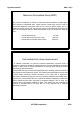
Operator manual REX-***R(F) 5.2 Highvoltage generator 1) REX-RF MODEL REX-850RF REX-650RF REX-550RF REX-525RF Phase 3Ø 3Ø 3Ø 3Ø Voltage (±10%) 400VAC 400VAC 400VAC 400VAC Frequency 50/60Hz 50/60Hz 50/60Hz 50/60Hz Power Input KVA 100KVA 80KVA 62.
Operator manual REX-***R(F) 2) REX-***R GENERATOR MODEL REX-1050 REX-650 REX-550 REX-525 REX-325 REX-125 R R R R R R Phase 3Ø 3Ø 3Ø 1 Ø /3Ø 1 Ø /3Ø 1Ø Voltage (±10%) 400VAC 400VAC 400VAC 220V/ 400VAC 220/ 400VAC 220/ 400VAC Frequency 50/60Hz 50/60Hz 50/60Hz 50/60Hz 50/60Hz 50/60Hz Power Input KVA 90KVA 80KVA 62.5KVA 50KVA 40KVA 12.
Operator manual REX-***R(F) 5.3 X-ray tube Tube Model Inherent filtration LTN-50(E7252X) 0.9mm Al eq. 0.9`mm Al eq. Intermittent Fixed added filtration 1.0mm Al eq. LTN-25(E7239X) Continuous 2.0mm Al eq. Intermittent 1.0mm Al eq. Continuous 2.0mm Al eq. Operating Tube voltage 40 to 150 kV Max. 40 to 125 kV Max. Focal spot 0.6 / 1.2 mm 1.0 / 2.
Operator manual REX-***R(F) 5.5 Patient table ▣ Model Group KOB-1 KOB-3 KOB-60 DMT-80 1) KOB-1, KOB-3, KOB-60 Item Specification KOB-1 KOB-60 Table base 4-way Floating Top Bucky Table Operated by Sensor 1260mm×500mm KOB-3 4-way Floating Top Bucky Table Operated by Foot Switch 1260mm×500mm 1108mm×859mm Table Top 2100mm×735mm 2100mm×735mm 2130mm×685mm Table Top Height 737mm 737mm min.560mm~max.
Operator manual REX-***R(F) 2) DMT-80 Specification Item DMT-80 Film Format& Exposure program 8*10″(20㎝×25㎝), 10*12″(25㎝×30㎝), 11*14″(28㎝×35㎝), 14*14″(35㎝×35㎝) Spot Film device Traditional spot film device Grid Ratio 8:1, Density 40lines/cm (Option -10:1 / 47lines/cm) Travel range of spot film device Longitudinal Travel : Approx. 55cm Lateral travel : Approx.
Operator manual REX-***R(F) 5.6 Tube stand ▣ Model Group SFC-31R SFC-31 SFM-31 CSTS-28 1) SFC-31(R) BS-20 Dimension-approx. Specification Item SFC-31R SFC-31 Counter Balance System Weight Balance Weight Balance Minimum/Maximum ceiling height 2300mm/2790mm [90.5"/109.8"] 2500mm/2990mm [98.4"/117.7"] Floor Rail 3500(3000*)mm [137.8(118.1*)"] 3500(3000*)mm [137.8(118.1*)"] ceiling Rail 3000mm[118.1"] 3000mm[118.
Operator manual REX-***R(F) 2) SFM-31 Item Specification Counter Balance System Weight Balance Minimum ceiling height 2250mm[88.6"] Rails Floor Rail Approx. 3050mm Longitudinal Travel Approx. 2500mm Vertical Travel Approx. 1500mm Transverse Travel Approx.
Operator manual REX-***R(F) 3) X-ray tube stand(CSTS-28) Item Specification Counter Balance System Spring Balance Minimum ceiling height 2500mm*1[98.4”*1] Rails Transverse Rail(Standard) 2400mm*2[94.5”2] Longitudinal Rail(Standard) 3000mm*2[118.1“*2] Longitudinal Travel(Standard) Approx. 2420mm5.0“*2] Vertical Travel Approx. 1450mm[57.1“] Transverse Travel(Standard) Approx. 3430mm6.
Operator manual REX-***R(F) 5.7 Bucky stand 1) BS-20 Item Specification Counter Balance System Weight Balance Minimum ceiling height 2050mm[80.7“] Vertical Travel Approx. 1105mm[43.5“] Front plate to film distance Approx. 30mm Film formats From 127mm×177.8mm to 355.6mm×431.8mm [5"×7" to 14"×17"] Cassette Cassette Insertion Can be loaded from both sides Vertical Carriage maximum load Approx. 15kg[33.
Operator manual REX-***R(F) 5.8 Physical characteristics Item Dimension(mm) Weight(kg) approxi. Approxi. High voltage generator W500×D500×H933 138 Controller W356×D262×H60 1.
Operator manual REX-***R(F) 5.
Operator manual REX-***R(F) ▣ Appendix 1 : Exposure factor 구분 촬영명 kVp 72 AP 70 SKULL Lateral 70 town's 50 PA HEAD Mandible Axial Lateral 50 68 town's 43 Nasal Bone Lateral 43 Zygomatic arch axial 70 Waters 70 Caldwell PNS 70 Lateral 70 Law FACIAL 65 Mastoid Stenvers 70 Townes 72 Lateral T-M joint town's 71 45 AP 65 PA Chest Lateral 65 APICO 65 CHEST 55 AP Rib(upper) Both oblique 60 55 AP Rib(lower) Both oblique 60 55 Supine 55 Erect 55 KUB 55 AP ABDOMEN Pelvis Lateral 60 53 AP Hip Lateral 55 55 decubitus
Operator manual Part number REX-***R(F) Trade name Type/Model Ratings Primary fuse AMP-TRAP (Power module F1,F2,F3) AJT50 50A,600V Accessible fuse WEBER Main power board F1,F7 6×32mm 250V, 6.3A(F1) 250V,10A(F7) Accessible fuse Main power board F2 WEBER 6.3×32T 250V, 6.3A Accessible fuse Main power board F3 WEBER 6.3×32T 250V, 4A Accessible fuse Main power board F4,F5,F6 WEBER 6×32mm T 250V, 2.5A(F4.5) 250V,6.3A(F6) Accessible fuse Power board F1,F2 WEBER 5×20mm 250V, 3.
Operator manual REX-***R(F) ▣ Appendix 2; Electrical component parts list Part number Trade name Type/Model Ratings Capacitor Power Module SAM WHA QMS-100H00100A 1000VDC, 10 µF Capacitor Power Module Digital Tech DMB-4EJ04E 450V, 4.
Operator manual REX-***R(F) Part number Trade name Type/Model Ratings BI-SONIC Technology 9P-230HS 230VAC,50/60HZ 16/14W SMPS(ps1) Fine suntronics VSF30-BDW Input : 85~264VAC,0.7A Out put : CH1 5VDC,0.3~3.0A CH2 12VDC, 1.2A Noise Filter OKY BT2AB-2010 250V,10A,50/60Hz IPM MITSUBISHI PM300DSA120 1200V,300A X-ray Tube Housing TOSHIBA E7239X 3 Phase Tilting Motor SI DAE ELECTRONICS SDT-0084 Table transformer T1 S.J S.J transfomer Bucky transformer T2 S.J S.
Operator manual REX-***R(F) After Service : LISTEM Corporation 1644-1, Donghwa-Ri, Munmak-Eup, Wonju-Si, Gangwon-Do, 220-801 TEL) 033-740-8322 FAX) 033-740-8400 E-mail) ibd@listem.co.