Form P-RG/RP/RBL (Version C) Obsoletes Form P-RG/RP/RBL (Version B) Applies to: Replacement Parts for Model Series RG, RP, HRPD, RGB, RPB, RGBL, RPBL, RPDBL, PGBL, RBA, RBHA, and RBL (including prefixes "C", "H", and "HC") IMPORTANT 1. Always include complete heater model and serial number so that any specification change can be considered for parts shipment. It can save time and expense. 2. Specifications are subject to change without notice. 3.
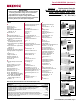
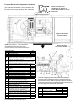
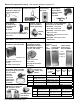
Duct Furnace Rating Plate REZNOR MERCER, PA. USA 16137 Made in Mexico DUCT FURNACE CATEGORY I FOR INDUSTRIAL/COMMERCIAL USE ONLY ANSI Z83.8 [ AA ] - [ A ] CGA 2.6 [ AA' ] -M [ A' ] DUCT FURNACE MODEL [ B ][ C ] SERIAL NO. [ D ] [ E ] VOLTS [ E ] PH [ E ] HZ MAXIMUM TOTAL INPUT [ E ] AMPS TYPE OF GAS: [ F ] [ G ] ORIFICE SIZE [ J ] DRILL HAS BEEN FACTORY ADJUSTED FOR USE AT [ H ] FEET [ I ] METERS OF ALTITUDE. SEA LEVEL ALT. ADJUSTED NORMAL INPUT [ R ] [ K ]BTU/HR.
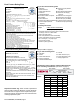
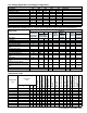
First Element of the Serial Number - Date of Manufacture Year 1989 1990 1991 1992 1993 1994 1995 1996 1997 1998 1999 2000 2001 2002 2003 2004 2005 2006 2007 2008 2009 2010 2011 2012 2013 2014 2015 2016 2017 2018 2019 2020 Jan AOA APA AQA ARA ASA ATA AUA AVA AWA AXA AYA AZA BAA BBA BCA BDA BEA BFA BGA BHA BIA BJA BKA BLA BMA BNA BOA BPA BQA BRA BSA BTA Feb AOB APB AQB ARB ASB ATB AUB AVB AWB AXB AYB AZB BAB BBB BCB BDB` BEB BFB BGB BHB BIB BJB BKB BLB BMB BNB BOB BPB BQB BRB BSB BTB Date Series was Introd
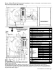
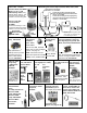
Dual Duct Furnace and Packaged System (Blower/Furnace) Model Configurations Outdoor Dual Duct Furnaces in Series, Model Outdoor (H)(C)RGB and (H)RPB Packaged Systems 1. Model RG, CRG, HRG, HCRG, RP, or HRP duct HRPD 250, 300, 350, 400, 500, 600, 700, 800 250 = 2(HRP125); 300 = 2(HRP150); 350 = 2(HRP175); 400 = 2(HRP200); furnace coupled with a "B" Blower Cabinet. 500 = 2(HRP250); 2.
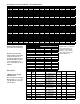
Line Voltage Application to Package Configuration Unit Voltage RG Control Volts In/Out/VA RGB Motor Voltage RGB Controls Volts In/Out/VA RP Control Volts In/Out/VA HRPD Control Volts In/Out/VA RPB Motor Voltage RPB Controls Volts In/Out/VA RPBL/RGBL/PGBL 400 RPBL/RGBL 500-800; PGBL 800 RPBL/RGBL 1050-1200; PGBL 1200 Line Voltage to Furnace or Packaged System 115 208 230 460 575 115/24/20 208/24/20 230/24/20 460/24/20 N/A 115 208 230 460 575 115/24/40 208/24/40 230/24/40 460/24/40 575/24/200 115/24/40 208/2
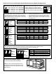
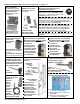
Furnace Electrical Component Locations ("B" Cabinet is illustrated; control locations are the same in the larger capacity "BL" Cabinets) Venter assembly and combustion air switch on indoor Model PGBL is on top 3B of the unit. Optional Downturn Plenum Cabinet NOTE: See pages 8 - 10 for illustrations and additional information about the furnace electrical components listed below.
Blower Cabinet Electrical Component Location ("B" Cabinet is illustrated; control locations are the same in the larger capacity "BL" Cabinets) Optional Downturn Plenum Cabinet See Note at the bottom of the page about building management control option. Code Description P/N 25 Fuse Holder (Fuse, see page 9) 60241 26 Convenience Outlet 96912 Blower Motor Contactor - 24V Coil 27A 216386 (replaces P/N 93661 and P/N 119625) 27B Blower Motor Starters - see P/N's on pages 27-30.
Electrical Components - See location drawings on pages 6-7. Code 1 - Electrical Box and Cover (in the electrical compartment) Electrical Box, P/N 100108 (replaces 11965 Code 3 - Combustion Air Switch Replacement depends on date of manufacture and altitude: Code 2 - Freezestat, J/C #AI9AAF-2C, 25-225oF, P/N 126170, (replaces P/N 16108) For power vented models mfgd beginning 7/04, altitudes to 4000 ft, P/N 204327, setpoint 0.58 ± .05" w.c. ; altitudes above 4000 ft, order P/N 204328, setpoint .52 ± .05" w.
Codes 8, 9, 10 - Gas Pressure Switches Codes 8 & 9 - Low Gas Pressure Switch, P/N 93849 (Range 1-6" w.c.); P/N 149176 (Range 6-24" w.c.
Electrical Components (cont'd) - See location drawings on pages 6-7. Code 31 - Mixed Air Codes 29 and 30 - High Ambient Limit Control and Controller, P/N 16109 Outside Air or Return Air Controller, P/N 126170 Codes 34 & 35 24V, DPDT, Plugin Relay, P/N 211411 and Socket, P/N 211415 Code 32 Potentiometer, P/N 16110 Code 38 - Reverse Flow Limit, #60T11313154, P/N 103323 Bracket, P/N 18795 For units manufactured prior to 9/2011, order a replacement kit, P/N 263527, to replace relay.
Replacement Pilot All Furnaces Replacement Pilot Kits: Natural Gas P/N 110861 Propane P/N 110862 1N, 1P 6* 4 Code P/N 1N 61145 1P 61146 2N 2P 63088 37801 5145 9664 44675 112647 112648 3 5* 3 2N, 2P 4 5* 6* *Included in the replacement kit which covers several models of heaters; these parts are not used when replacing pilots on the heaters covered in this manual.
RG Cabinet and Flue Box Parts - Same parts apply to RG duct furnaces in packaged Model Series RGB and Series RGBL (Quantites listed are per furnace section.) Basic Exterior Parts for 72 Model RG Flue Collection Box for Basic Model RG Furnace 67 62 Flue Restrictors - Codes 56 & 81 See Codes 56 & 81 below for type and size. For application by unit size, see Code 56 or 81 in the table below.
Heater Bttm Left Side 68 Assembly (includes 68A & 68B as listed) 68A Heater Bottom Left Side Panel RG Sizes Propane 81 700, 400, 800, 1050 1200 300 350 400 100299 (includes 68B P/N 15021) 500 75 100 Natural Gas 1 68B Vinyl Grommet 72 73 74 75 76 77 78 79 80 Qty RGBL Sizes Code Description 125 150 175 200 225 600 250 100298 (includes 68B P/N 102607) 1 1 100298 (includes 68B P/N 102607) 100125 102607, #1020-K, 1/2" 1 --------15021, #1020, 3/4" 1 110053, 6" 61857, 8" 61866, 10" *61875 61875
Model RP Cabinet and Collection Box Parts - Same parts apply to RP duct furnaces in packaged Model Series HRPD, RPB, RPBL, & RPDBL (Quantities listed are per furnace section.
Model (C)(H)(HC)RP(B) Sizes Qty per Model RPBL Sizes furnace Model RPDBL Sizes section Model HRPD Sizes RP, HRP prior to Series 8 1 Flue Collection Box RP, HRP Series 8 1 Assembly CRP, HCRP - All (no Series 8) 1 Collection Box Side Gasket Strip 2 Collection Box Front and Rear Gasket Strip 2 Flue Duct Gasket 1 Flue Duct Assembly 1 Flue Duct Restrictor 1 For RP Series units with Option Gear Motor 1 AG39 or AG40 & 1st furnace Gear Mtr Capacitor, 15MFD 1 with Option AG41 or AG42 manufactured beginning 11/03 Tim
Heat Exchanger & Components - Applies to all Models (one heat exchanger per furnace section; directional baffles apply as listed) Heat Exchanger All Models Model (C)(H)(HC)RG/RP(B) Sizes Model RPBL, RGBL, PGBL Sizes Qty per furnace Model RPDBL Sizes section Model HRPD Sizes Aluminized Steel 1 Heat 409 Stainless Steel 1 Exchanger 321 Stainless Steel 1 Burner Rack Slide Rail 2 Burner Rack Back Brace 1 Gasket for Fan Control, Limit Control, Patch Plate 2 Patch Plate (not illustrated) 1 170 180 171A 171A 17
Model (C)(H)(HC)RG/RP(B) Sizes 75 100 125 150 175 200 225 250 300 350 400 Model RPBL, RGBL, PGBL Sizes 500 600 700, 1050 400, 800, 1200 Model RPDBL Sizes 1000 1200 1400 800 / 1600 500 600 Code Description Model HRPD Sizes 250 65972 300 65973 350 400 65974 65975 700 800 65976 65977 65978 65984 65985 65986 -- 92818 183 Burner Rack Aluminum with Carryovers & Air Shutters 184 Replacement Burner Rack Stainless Steel with Carryovers for RP units with Gas Control Optio
Special Manifolds Code Description P/N Components for Illinois School Code Manifold (Option BM12 is no longer required but was available on all sizes of RG, RP, RGB, RPB, RGB, RPBL, and PGBL 205 Low Gas Pressure Switch, see page 9, Code 8 or 9 206 High Gas Pressure Switch, seee page 9, Code 10 207 Vent Limiter, Maxitrol A1209, see page 9 208 Pressure Switch Brackets (3-7)100261 209 Manual Gas Valve (one per unit), page 17 210 Manual Pilot Shutoff (one per unit), page 17 211 Safety Solenoid Valve (one per un
Cabinet Parts for "B" Type Blower Cabinet Section - Applies to Model Series RGB and RPB (For Blower Cabient Models RBA and RBHA, see pages 43-44.
Cabinet Parts for "B" Type Blower Cabinet Section - Applies to Models RGB & RPB (cont'd) Code 270A 270B 270C 271 272 273 273A 274 275 276 277 278 279 280 281 282 Model (C)(H)RGB/RPB Sizes Blower - Housing, Shaft, Wheel & Bearings Blower - Right Hand Housing & Wheel only Blower - Left Hand Housing & Wheel only Blower Shaft Blower Shaft Bearings Mtr Adjustment Brckt Assy - 1/4-3/4 HP Mtrs Hardware Bag only for Code 273 Motor Mounting Strap - for 1/4 - 3/4 HP Mtrs Motor Mounting Plate - 1-3HP Motor Motor Moun
Code Model RPBL, RGBL, PGBL Sizes Cabinet Bottom - Right Half - solid (no opening) Cabinet Bottom - Left Half - solid (no opening) 300 Cabinet Bottom - Right Half - return air opening Cabinet Bottom - Left Half - return air opening End Panel Assembly - solid (no opening) End Pnl Assy - solid (no opening) w/double-wall cnstrctn (Opt AY3) End Panel Assembly - 30% opening 301 End Pnl Assy - 30% opening w/double-wall construction (Opt AY3) End Panel Assembly - 100% opening Filter Cabinet Assembly - w/double-wal
Cabinet Parts for "BL" Type Blower Cabinet Section - Applies to RGBL, RPBL & PGBL (cont'd) Motor Mounting Bolts Blower & Bearing w/ 15 or 20 HP Motor 5/16" Bolt 3/8" Bolt Blower Triangular Bearing Mounting for RGBL/RPBL/PGBL with a 7-1/2 or 10 HP Motor Description Left Bearing support Assy Right Bearing Support Assy Pillowblock Bearing 1-3/16" 90° G
Code 373 - Bent Damper Rod, P/N 105420 NOTES: Crank Arm Code 380A is used with motors P/N 115682, 115683, & 115681 (motors used in currently manufactured units). Use Crank Arm P/N 20874 (illustrated), M/H #7616BR, with obsolete motors P/N 53928, 87059, and 96767. 377 P/N 20874 382 378 Code 388 - Mixed Air Controller, M/H T991-1004, P/N 16109 Code 387 Potentiometer, M/H 112894FA, P/N 16110 Grommet Clamp, P/N 39224 380A See note above.
Dampers and Controls (cont'd) Components by Option AR__ for currently manufactured (2012) Model RPB units. See linkage illustrations below. (For components of obsolete Option Codes, see "BL" chart, page 23.) (Refer to wiring diagram for applicable motorized AR Option.
DAMPER ARM P/N 12635 SET ARM AT 1 O'CLOCK BOLT DAMPER ARM ADJUSTMENT PLATE TO MOTOR ARM USING BOLT P/N 10393 (2) & NUT P/N 7328 (2) BALL JOINT TO INSIDE SET AT 45° P/N 12636 BALL JOINT TO INSIDE SET AT 45° - P/N 12636 DAMPER ARM P/N 12635 SET ARM AT 11 O'CLOCK SET ON MIDDLE PIN OF 3 BLADE DAMPER DETAIL A 17" LONG DAMPER ROD EVEN WITH BALL JOINT BOTH ENDS OUTSIDE AIR CLOSED DAMPER ARM ADJUSTMENT PLATE P/N 115687 SEE DETAIL A BALL JOINT TO INSIDE P/N 12636 P/N 112556 BALL JOINT TO INSIDE P/N 12636 BA
Damper Linkage by Option Code (cont'd) for units mfgd before Aug 2004 where indicated Illustration applies to units mfgd before Aug 2004 only. Form P-RG/RP/RBL, P/N 263984R2, Page 26 Illustration applies to units mfgd before Aug 2004 only.
Replacement Blower Motors, Starters, and Variable Frequency Drives Replacement Motors (Tables on pages 27-30) Motors in the Open, TEFC, and Premium Efficiency tables that are highlighted in gray do not have internal overload protection and must be used with the motor starter and overload listed in the table. Refer to the wiring diagram for applicable AL and AN or VFD option codes. See Code 27, page 9, for standard motor contactor (Option AN2), P/N 216386, for motors with internal overloads.
Replacement Blower Motors and Starters (cont'd) - See replacement information, top of page 27. Type HP 2 2 2 2 2 2 2 3 3 3 3 3 3 5 5 5 5 5 5 7.5 7.5 7.5 7.5 7.5 7.5 10 10 10 10 10 10 15 15 15 15 20 20 20 20 AL Type HP AL TEFC 1/4 19 TEFC 1/3 20 TEFC 1/2 21 TEFC 3/4 22 TEFC 1 23 Open Open Open Open Open Open Open 8 9 10 11 12 15 16 Open Motor Mfr's #.
Type HP AL TEFC 1 23 1.5 24 2 25 3 26 5 27 7.5 32 10 33 15 34 20 35 (cont'd) (cont'd) TEFC TEFC TEFC TEFC TEFC TEFC TEFC TEFC TEFC TEFC TEFC TEFC TEFC TEFC TEFC TEFC TEFC TEFC TEFC TEFC TEFC TEFC TEFC TEFC TEFC TEFC TEFC TEFC TEFC TEFC TEFC TEFC TEFC TEFC TEFC TEFC TEFC TEFC TEFC TEFC Type EE EE EE EE EE EE EE EE EE EE EE EE EE EE EE EE EE EE EE EE EE EE EE EE EE EE EE EE HP AL 1 36 1.5 37 2 38 3 39 5 40 7.5 41 10 42 TEFC Motor Mfr's #.
Replacement Blower Motors and Starters (cont'd) - See replacement information, top of page 27. Type EE EE EE EE EE EE EE EE HP AL 15 43 20 44 Premium Efficient Motor Mfr's #. P/N EFM2513T-8 142440 EFM2513T 142441 EFM2513T 142441 EFM2513T-5 142289 E452-F2 159187 EFM2515T 142299 EFM2515T 142299 EFM2515T-5 142300 fla 40.7 35.4 17.7 16.0 57.0 47.0 23.5 19.2 2-Speed Blower Motors Replacement Parts for NEMA Starters Starter (AN10) Frame Service Power ph Size Factor Factor Mfr # P/N 3 254T 1.
Drive Options and Components OPT RPM OPT RPM OPT RPM OPT RPM Range Range Range Range Drive components include the belt, motor pulley, blower pulley, and bushings, if required. The table at the right identifies the RPM range AM2 451-500 AM8 751-800 AM14 1051-1100 AM19 1301-1350 AM3 501-550 AM9 801-850 AM15 1101-1150 AM20 1351-1400 of the drive option. Drive options are listed by AM No. AM4 551-600 AM10 851-900 AM16 1151-1200 AM21 1401-1450 (NOTE: Components listed are for currently used motors.
Drives - Model Series (H)(C)RGB, (H)(C)RPB, and Blower Cabinet Model RBA (cont'd) Drive Components for Open Motors (cont'd) Unit Sizes 250 Motor HP Opt AK2 (208/1); AK3 (230/1 3 AL9 5 AL10 3/4 AL5 1 AL6 300 cont'd 1-1/2 AL7 350 400 Voltage Option 2 AK5 (208/3); AK6 (230/3); AK7 (460/3); AK8 (575/3) AK1 (115/1); AK2 (208/1); AK3 (230/1); AK5 (208/3); AK6 (230/3); AK7 (460/3) AL8 AK5 (208/3); AK6 (230/3); AK7 (460/3) AK2 (208/1); AK3 (230/1) 3 AL9 5 AL10 AK5 (208/3); AK6 (230/3); AK7 (46
Unit Sizes Motor HP Opt 1/2 AL21 3/4 AL22 1 AL23 AK1 (115/1); AK2 (208/1); AK3 (230/1); AK5 (208/3); AK6 (230/3); AK7 (460/3); AK8 (575/3) AK1 (115/1); AK2 (208/1); AK3 (230/1); AK5 (208/3); AK6 (230/3); AK7 (460/3) 250 300 Voltage Option 1-1/2 AL24 AK8 (575/3) 2 AL25 3 AL26 3/4 AL22 1 AL23 AK5 (208/3); AK6 (230/3); AK7 (460/3); AK8 (575/3) AK1 (115/1); AK2 (208/1); AK3 (230/1); AK5 (208/3); AK6 (230/3); AK7 (460/3) AK1 (115/1); AK2 (208/1); AK3 (230/1); AK5 (208/3); AK6 (230/3); AK7 (4
Drives - Model Series (H)(C)RGB, (H)(C)RPB, and Blower Cabinet Model RBA (cont'd) Drive Components for Two-Speed Motors (See drive information, top of page 31.
Drive AM Nos. Motor Pulley Blower Pulley Belt *Shaft (See Key, chart on page 31) P/N Mfr # Bore P/N Mfr # Bore P/N Qty Mfr # Centerline **AM 15, 16, 17, 18, 19, 20 89644 3MVPP40-B54 1-5/8 106258 3TB66HG 1-7/16 92224 3 B56 20.47 **15 AL15 **AM 21, 22, 23, 24 89644 3MVPP40-B54 1-5/8 106262 3BK65HC 1-7/16 92224 3 B56 20.53 **20 AL16 **AM 17, 18, 19, 20, 21, 22, 23, 24 89644 3MVPP40-B54 1-5/8 106262 3BK65HC 1-7/16 92239 3 BX54 20.
Drive Components for Premium Efficiency Motors (cont'd) Drive AM Nos. Motor Pulley (See Key, chart on page 31.
Replacement Filters - Model Series RGB and RPB and Blower Cabinet Model RBA Filter Arrangements APPLICATION NOTES: Do not use flat disposable filters on Models 75-125 with over 2999 CFM; on Models 150-175 with over 4499 CFM, or Models 200-225 with over 4999 CFM; on Models 250-300 with over 5499 CFM; on Model 350 with over 6499 CFM; or on Model 400 with over 7399 CFM. Do not use pleated filters on Models 75-125 with over 3999 CFM.
Replacement Filters/Blockoff Plates - currently manufactured "BL" Cabinets Filter Arrangements for 1" or 2" Disposable Filters (Options AW2 and AW7) A B C D 16 x 16 16 x 25 12 x 25 12 x 30 Blockoff Plates: (1) P/N 106334; (4) P/N 114337 RBL; PGBL, (C)RGBL, RPBL 400, 800, 1200; & RPDBL 800, 1600 (2 sets) A B C D 16 x 16 16 x 25 12 x 20 12 x 25 A B C 16 x 25 12 x 20 12 x 30 Blockoff Plates: (1)
Optional Remote Console Optional RC style remote console includes a mounting ring so that the console may be either recessed or wall mounted. The box is of 16 gauge steel with knockout holes for field wiring. The cover is made of plastic with custom engraving. Order replacement parts for Option RC remote console by part number.
Optional Outside Air Inlet Hood (Weatherhood) Model RPBL, RGBL Sizes Code Model (C)(H)RGB/RPB Sizes 75/100/125 150/175/RBA 200/225 250/300 Complete 100% Outside Air Inlet Hood 106201 106202 106203 106204 Weatherhood Left Side 100216 Weatherhood Right Side 100217 Weatherhood Top 100227 100228 100229 100230 Weatherhood Bottom 100234 100235 100236 100237 Louver Assembly 103773 103774 103775 103776 30% Outside Air Inlet Hood Assembly 501 105117 105118 105119 105120 (part of Options AR6 and AR7) 501A 30% Air
Code 570A 570B 571 572 573 574 575 576 577 578 579 580 581 582 Code 583 584 585 586 587 588 590 591 592 593 594 595 596 597 598 599 600 601A 601B Model RPBL, RGBL, PGBL Sizes Model (C)(H)RGB/RPB Sizes 75, 100,125 Description *Opt AU Construction 172314 Coil Cabinet Top -Top Filler (between top sections) -Gasket for Top Filler (under 571) -2, 3, 11, 12, Single and 13, 14 Double Wall Inner Top Support Insulation -Inner Top Support -Top Insulation Retainer 172365 Top Insulation 172516 Plenum Cabinet Top 10
Optional Downturn Plenum and Discharge Damper - Applies to Model Series RGB/RPB, Model Series RGBL/RPBL, and Blower Cabinet Model RBL Assembled Replacement Downturn Plenum Cabinet less Curb Cap (no dampers) 75-125 150-175 RGB/ 200-225 RPB 250-300 Series 350 400 RGBL/ 500, 600 RPBL 750, 1050 Series 400, 800, 1200 Model RBL 511 "Attached" Downturn Plenum with Door Panel Removed 147140 147141 147142 147143 147144 147145 147147 147148 147146 147146 517 513 514 515 510 "Unattached" Downturn Plenum Assem
Model RBL/RBA/RBHA Blower Cabinets Blowers and Cabinet Parts Model RBA is a stand-alone blower cabinet comparable in size and capacity to the cabinet that is a factory-assembled portion of packaged Models RGB/RPB 150. Model RBHA is a Model RBA blower cabinet designed for special applications requiring inlet air temperatures above that recommended by the motor manufacturer. The blower motor, bearings, and adjustable drive are mounted in a weatherized housing external to the airstream.
Model RBL/RBA/RBHA Blower Cabinets - Cabinet Parts (cont'd) NOTE: Model RBL and RBA cabinet parts may be of either uninsulated single-wall construction, insulated single-wall construction, or double-wall construction which consists of two metal panels with insulation between. Select the replacement part that matches the original construction. Model RBHA is only available in insulated single-wall construction.