
Replacement Valves
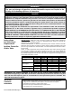
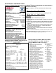
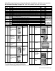
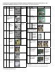
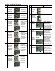
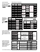
Table Of Contents
- SAFETY WARNINGS AND GUIDELINES FOR A QUALIFIED SERVICE TECHNICIAN
- Instructions for Selecting a Replacement Ignition Controller and/or Valve
- Serial Number and Model Codes
- Serial No. Decoding
- Serial Number Key - Month and Year of Manufacture
- Heater Serial No. PREFIX and SUFFIX Codes
- Model No. Decoding
- Safety Pilot or Ignition System Originally Supplied, Identified by Serial No. Code -- See Serial No. Decoding on pages 3-4. (N/A = Not available; see other notes below.)
- Type of Valve Originally Supplied -- See Serial No. Decoding on pages 3-4.
- Maxitrol Components for Electronic Modulation - Indirect-Fired Equipment Model Series X, SC, RG, RP, RX, RPV, and EEDU with Options AG7, AG8, AG9, AG21, AG39, AG40, AG41, or AG42

Form P-VALVES, P/N 263995, Page 3
Example of a Rating Plate that applies to most Reznor
®
Models showing Model and Serial Numbers
Serial No. Decoding
DUCT FURNACE
CATEGORY I
FOR INDUSTRIAL/COMMERCIAL USE ONLY NRTL
DESIGN CERTIFIED UNDER ANSI Z83.8a-1998
DUCT FURNACE
MODEL HX100E-8-S OCT 2004
SERIAL# EBDJ66W8N12345
115 VOLTS 1PH 60HZ MAXIMUM TOTAL INPUT .5AMPS
TYPE OF GAS NATURAL
ORIFICE SIZE #41 DRILL HAS BEEN FACTORY ADJUSTED
FOR USE AT 0-2000 FEET (0-610 METERS) OF ALTITUDE
SEA LEVEL ALT ADJUSTED
NORMAL INPUT 100000 100000 BTU/HR
OUTPUT CAPACITY 80000 80000 BTU/HR
MIN. INPUT (2, M, MB, MV MODELS) 50000 50000 BTU/HR
NORMAL MANIFOLD PRESSURE 3.5 IN. W.C.
MIN. PERMISSIBLE GAS SUPPLY PRESSURE
FOR PURPOSE OF INPUT ADJUSTMENT 5.0 IN. W.C.
MAXIMUM THROUGHPUT 3704 CFM
MINIMUM THROUGHPUT 988 CFM
CLEARANCE TO COMBUSTIBLE CONSTRUCTION: TOP - 6";
FLUE CONNECTION - 6"; SERVICE SIDE - WIDTH OF UNIT;
OPPOSITE SIDE - 6"; BOTTOM - 3", MAY BE INSTALLED ON
NONCOMBUSTIBLE FLOORS.
INSTALL ON THE POSITIVE PRESSURE SIDE OF AIR
CIRCULATING BLOWER.
THIS UNIT MAY BE INSTALLED DOWNSTREAM FROM A
REFRIGERATION SYSTEM (USE DRAIN OPTION CS1).
FOR ALTERNATE INSTALLATION, USE THE LATEST OF THE
APPROPRIATE STANDARDS LISTED BELOW:
FOR AIRCRAFT HANGARS USE STANDARD ANSI/NFPA 409
FOR PARKING STRUCTURES USE STANDARD ANSI/NFPA 88A
FOR REPAIR GARAGES USE STANDARD ANSI/NFPA 88B
Mercer, PA 16137
Serial Number and Model Codes
Sample of a Serial No. for Units manufactured from 1963 through
1974:
OA 1 2 N 693 Serial No.
1 2 3 4 5 Element
Sample of a Serial No. for Units manufactured beginning in 1975:
BDJ 66 W8 N 12345 Serial No.
1 2 3 4 5 Element
Element Key:
1 = Month and Year of manufacture; see page 4.
2 = Type of safety pilot or ignition system; see pages 6-10 for Code
explanation.
3 = Type of valve; see pages 12-22 for Code explanation and illustra-
tions on pages 23-27. (A dash indicates that the valve was eld
supplied.)
4 = Type of gas that the heater was originally manufactured to burn
D = Dual fuel, natural and propane; L = Propane; N = Natural
(Check for gas conversion label.)
5 = Consecutive number of heater manufactured. Used for identi-
cation purposes only.
In addition to the basic ve elements, the serial number may also include
prex and/or sufx codes. See page 5 for a listing and explanation of
these codes. All codes apply to original equipment only.
REZNOR
®
MERCER, PA, U.S.A. 16137
MADE IN USA
FOR INDUSTRIAL/COMMERCIAL USE ONLY
SUITABLE FOR OUTDOOR USE
MODEL [ A ] [ B ]
SERIAL NO. [ ]
ELECTRICAL
[D] VOLTS +/- 10% [D] PHASE [D] HZ
MINIMUM CIRCUIT AMPACITY (MCA) [ F ] AMPS
MAXIMUM FUSE SIZE/*CKT BREAKER [ G ] AMPS
QTY FLA (EA) HP (EA)
SUPPLY AIR BLOWER MOTOR 1 [ E ] [ C ]
CONDENSER FAN MOTOR (S) [ T ] [ U ] [ Z ]
QTY RLA (EA) LRA (EA)
COMPRESSOR A [ H ] [ I ] [ J ]
COMPRESSOR B [ K ] [ L ] [ M ]
COMPRESSOR C [ N ] [ O ] [ P ]
COMPRESSOR D [ Q ] [ R ] [ S ]
COMPRESSOR E [ GG ] [ HH ] [ II ]
CIRCUITS A B C D E
REFRIGERANT - R-410a CHARGE - LBS
[ V ] [ W ] [ X ] [ Y ] [ JJ ]
TEST PRESSURES HIGH 600PSIG LOW 45PSIG
EQUIPPED FOR OPERATION AT AN AIR FLOW OF [ CC ] SCFM
AGAINST A STATIC PRESSURE OF [ DD ] INCHES WATER COLUMN
DRIVE RPM [ EE ]
WIRE DIAGRAM [ FF ]
REFER TO RATING PLATE IN THE FURNACE SECTION (WHEN USED)
FOR ADDITIONAL INFORMATION.
*HACR TYPE REQUIRED PER NEC
Rating Plate Key for MAPS
®
Model Series RCA,
RDA, RCB, RDB, RCC, and RDC: (NOTE: To
decode a MAPS Serial No., see page 4.)
Example of a Reznor
®
MAPS
®
Unit Rating Plate
Showing Model and Serial Numbers
CC = SCFM Airow
DD = External
Static Pressure
(“ w.c.)
EE = Drive (Option
AM)
FF = Wiring Dia-
gram No.
GG = Quantity -
Compressor E
HH = Rated Load
Amps of Com-
pressor E
II = Locked Rotor
Amps of Com-
pressor E
JJ = Refrigerant
Charge (lbs) -
Circuit E
A = Model
B = Manufacturing Date (Month/Year)
C = Blower Motor HP
D = Volts/Phase/Hertz
E = Full Load Amps (FLA) of Blower Motor
F = Minimum Circuit Ampacity (MCA)
G = Maximum Fuse Size (MOP)
H = Quantity - Compressor A
I = Rated Load Amps of Compressor A
J = Locked Rotor Amps of Compressor A
K = Quantity - Compressor B
L = Rated Load Amps of Compressor B
M = Locked Rotor Amps of Compressor B
N = Quantity - Compressor C
O = Rated Load Amps of Compressor C
P = Locked Rotor Amps of Compressor C
Q = Quantity - Compressor D
R = Rated Load Amps of Compressor D
S = Locked Rotor Amps of Compressor D
T = Quantity Condenser Fan Motors
U = Rated Load Amps of Condenser(s)
V = Refrigerant Charge (lbs) - Circuit A
W = Refrigerant Charge (lbs) - Circuit B
X = Refrigerant Charge (lbs) - Circuit C
Y = Refrigerant Charge (lbs) - Circuit D
Z = Condenser Fan Motor HP