
Installation Manual

CODE
in
FIGURE
2
Clearance to
Combustibles
Natural Gas Models Propane Models
RIHN 30
X
RIHN 60
Y
RIHVN 100
Z
RIHVN 150 RIHVN 160
Z
RIHVN 200 RIHL 50
Z
RIHVL 90
Z
RIHVL 120
Z
inches mm inches mm inches mm inches mm inches mm inches mm inches mm inches mm inches mm
A
Side of Heater
B
Back of Heater
C
Top of Heater:
0RXQWHGQRKHDW
GHÀHFWRU
0RXQWHGRQO\QR
KHDWGHÀHFWRU
0RXQWHGZLWK+HDW
'HÀHFWRU2SWLRQ'2
1$ 1$ 1$ 1$
D
Below the Heater:
6WDQGDUG5HÀHFWRU
:LWK3DUDEROLF5HÀHFWRU
2SWLRQ'0
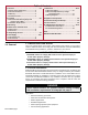
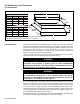
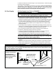
FIGURE 2 - Clearances to Combustibles (Inches and mm)
NOTES:
X
0RGHO5,+1LVQRWDYDLODEOHLQ&DQDGD
Y
0RGHO5,+1LQ&DQDGDUHTXLUHVDGGLWLRQRIDZLUHJULG
2SWLRQ'1
Z
6HHDOORZDEOHPRXQWLQJDQJOHVLQ3DUDJUDSK
B
A
A
C
D
B
D
C
E
E
B
D
C
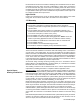
3D VIEW
ALL Sizes
STACKING HEIGHT
In locations used for the storage of combustible materials, signs shall be posted to specify the maximum permissible
stacking height to maintain required clearances from the heater to combustibles. (ANSI Z233.1/NFPA 54)
The stated clearance to combustibles represents a surface temperature of 90°F (50°C) above room temperature.
Building materials with low heat tolerance (such as plastic, vi
nyl siding, canvas, tri-ply, etc.) may be subject to
degradation at lower temperatures. It is the responsibility of the installer to assure that adjacent materials are
protected from degradation (ANSI Z83.19).
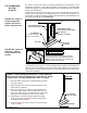
It is recommended more distance than the minimum clearance be maintained above the unit whether or not the
construction is combustible to reduce and/or eliminate hot spots and possible staining of painted ceiling surfaces.
If the unit must be close to the roof or ceiling, interpose a non-co
mbustible baffle (twice the size of the reflector)
between the unit and the roof or ceiling. Allow at least 2” (5cm) between the roof or ceiling and the non-combustible
baffle. Allow at least 12” (31cm) between the non-combustible baffle and the top of the heater.
D
H
M
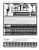
Sizes 30, 50, & 60 ONLY
A - D See Table below.
E 0RXQWLQJ$QJOH
H 6WDFNLQJ+HLJKWHTXDOV0'
M 0RXQWLQJ+HLJKW6HHWDEOHRQSDJH
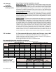
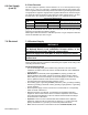
5.0 Suspending
the Unit
Unit Weight and Allowable Mounting Angle
%HIRUH LQVWDOOLQJ WKH XQLW FKHFN WKH VXSSRUWLQJ VWUXFWXUH WR GHWHUPLQH WKDW LW KDV
VXI¿FLHQWORDGFDUU\LQJFDSDFLW\WRVXSSRUWWKHweight.
0RXQWLQJDQJOHPXVWEHZLWKLQWKHWROHUDQFHDOORZHG
Model RIHN 30 RIHL 50 RIHN 60 RIHVL 90 RIHVN 100 RIHVL 120 RIHVN 150 RIHVN 160 RIHVN 200
Net Wt -
lbs (kg)
Single-Stage
Two-Stage
Allowable Mounting
Angle Tolerance
P/N 131793R11, Page 7