
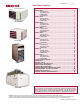
Brochure


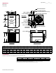

Top View
Rear View
Front View
Right Side View
A
B
E
F
G
H
J
K
M
N
R
P
C
25”
(635mm)
5-5/8” (143mm)
1-9/16” (40mm)
Condensate Drain
4” Vent Connection
Line Voltage Entrance
(connects in sealed electrical box)
6” Combustion
Air Connection
Disconnect Switch
Thermostat
Connection
8-1/4” (210mm)
3-1/4” (83mm)
1-1/4” (32mm)
Four
Suspension
Points
(3/8-16 Female
Thread)
23” (584)
LED Viewport
External Gas Connection
S
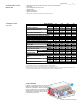
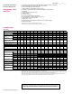
Size A B C E F G H J K M N P R S
Dimensions-inches(±1/8inch)
130, 180 20 1/8 39 3/16 16 1/16 11 15/16 2 3/8 25 11/16 50 1/2 42 13 7/16 8 5/16 4 5/16 5 1/16 6 5/16 1 3/4
260, 310 34 1/8 40 15/16 30 1/16 13 15/16 1 3/8 27 11/16 53 5/16 44 14 7/32 9 3/32 5 1/16 18 15/16 7 3/4 1 3/8
Dimensions-mm(±3mm)
130, 180 (511) (995) (408) (303) (60) (652) (1,283) (1,067) (341) (211) (110) (129) (160) (44)
260, 310 (867) (1,040) (764) (354) (35) (703) (1,354) (1,118) (361) (231) (129) (481) (197) (35)
DIMENSIONS
Model UEAS
±1/16" (2mm)
Top Flue Connector Access Panel
A
Non-Access Side Bottom
B
Rear
C
inches (mm) inches (mm) inches (mm) inches (mm) inches (mm) inches (mm)
4 (102) 6 (152) 18 (457) 2 (51) 1 (25) 18 (457)
CLEARANCES
Clearances required from combustible material unless otherwise noted.
A
Access Panel clearance required for access to controls for service.
B
Bottom clearance to combustible. Heater should be suspended a minimum of 5 feet (1.5M) above the oor.
C
Rear clearance required for air ow. Clearance should be measured from the fan motor.
Form RZ-C-UH (Version H) Page 4
Page Number _______ of ______