
Brochure


● Single-stage, propane gas valve (eld adjustable for operation to 9,000 ft. elevation
B
)
● Two-stage natural gas or propane gas valve - Sizes 60-400
● 409 or 316 Stainless steel heat exchangers
● Totally enclosed fan motor (Sizes 30-250, 115V only)
● Horizontal or Vertical Combustion Air/Vent Kit including concentric adapter
● Thermostat
● Thermostat guard with locking cover
● Vertical louvers
● Downturn nozzle kits
● Gas conversion kits (natural and propane)
● Primary/secondary controls for zoning up to six units
● Ceiling suspension kit - Sizes 30-125
● Hanger kits for 1” pipe
● Stepdown transformer (for 208/115, 230/115 or 460/115 supply voltage)
● Manual shutoff valves
B
Pressure switch change required for installations above 6,000 ft.
C
Selection of either a horizontal or vertical combustion air/vent kit is required.
OPTIONAL FEATURES -
FACTORY INSTALLED
ACCESSORIES - FIELD
INSTALLED
D
CSA rating for altitudes to 2000 ft.
E
Size shown is for gas connection to a single stage gas valve, not supply line size.
F
Smaller and/or larger vent and combustion air pipe diameters may be allowed; refer to the Venting Installation Manual for Separated Combustion
Units, Form I-V-SC. If vent diameter is different from vent connection, reducer/enlargers will be eld-required.
G
MOP = 2.25 x largest motor FLA + remaining load. Answer is rounded down to the next size of commercially available circuit breaker or fuse.
H
All other information in this table is based on a heater equipped with a standard 115 volt open fan motor.
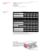
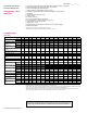
Size 30 45 60 75 100 125 150 175 200 225 250 300 350 400
Input Heating Capacity
BTUH 30,000 45,000 60,000 75,000 105,000 120,000 150,000 175,000 200,000 225,000 250,000 300,000 350,000 400,000
(kw/h) (8.8) (13.2) (17.6) (22.0) (30.8) (35.2) (44.0) (51.3) (58.6) (65.9) (73.3) (87.9) (102.6) (117.2)
Thermal Efficiency (%) 82 83 83 83 83 83 83 83 83 83 83 83 83 83
Output Heating
Capacity
D
BTUH 24,600 37,350 49,800 62,250 87,150 99,600 124,500 145,250 166,000 186,750 207,500 249,000 290,500 332,000
(kw/h) (7.2) (10.9) (14.6) (18.2) (25.5) (29.2) (36.5) (42.6) (48.7) (54.7) (60.8) (73.0) (85.1) (97.3)
Gas Connection
(inches)
E
Natural 1/2 1/2 1/2 1/2 1/2 1/2 1/2 1/2 1/2 3/4 3/4 3/4 3/4 3/4
Propane 1/2 1/2 1/2 1/2 1/2 1/2 1/2 1/2 1/2 3/4 3/4 3/4 3/4 3/4
Vent Connection
F
(inches
diameter)
4 4 4 4 4 4 5 5 5 5 5 6 6 6
Combustion Air Inlet
F
(inches
diameter)
4 4 4 4 4 4 6 6 6 6 6 6
6 6
Control Amps (24 volt) 1.0 1.0 1.0 1.0 1.0 1.0 1.0 1.0 1.0 1.0 1.0 1.0 1.0 1.0
Full Load Amps (115 volt) 1.9 2.4 2.4 3.3 3.9 5.1 3.8 3.8 4.6 7.5 7.5 11.0 11.0 11.0
Maximum Over Current Protection
(115V)
G
15 15 15 15 15 15 15 15 15 15 15 20
20 20
Normal Power Consumption (watts) 109 155 155 217 276 354 392 392 491 747 747 1086 1086 1086
Discharge Air Temperature Rise
(°F)
50 55 60 60 60 60 60 60 60 60 60 60 60 60
Air Volume
CFM 456 629 769 961 1345 1537 1921 2242 2562 2882 3202 3843 4483 5123
(M
3
/min) (12.9) (17.8) (21.8) (27.2) (38.1) (43.5) (54.4) (63.5) (72.5) (81.6) (90.7) (108.8) (126.9) (145.1)
Discharge Air Opening
Area
ft
2
0.96 0.96 1.25 1.25 2.01 2.01 2.56 2.56 2.56 3.51 3.51 4.79 4.79 4.79
(M
2
) (0.09) (0.09) (0.12) (0.12) (0.19) (0.19) (0.24) (0.24) (0.24) (0.33) (0.33) (0.45) (0.45) (0.45)
Output Velocity
FPM 475 656 616 770 668 763 752 877 1003 820 911 802 936 1069
(M/min) (145) (200) (188) (235) (204) (233) (229) (267) (306) (250) (278) (244) (285) (326)
Fan Motor HP
H
Open 0.02 0.03 0.03 0.06 1/30 1/20 1/6 1/6 1/6 1/4 1/4 1/2 1/2 1/2
Enclosed 0.06 0.06 0.06 0.06 1/20 1/20 1/4 1/4 1/4 1/4 1/4 1/2 1/2 1/2
Fan Motor RPM 1550 1550 1550 1550 1050 1050 1050 1050 1050 1050 1050 1050 1050 1050
Fan Diameter inches 10 10 12 12 16 16 18 18 18
20 20 24 24 24
Sound Level
dba @
15 ft
40 40 40 49 54 55 51 52 53 56 56 59 61 62
Approximate Net
Weight
lbs 55 60 68 73 97 102 173 188 188 204 216 270 295 307
(kg) (25) (27) (31) (33) (44) (46) (78) (85) (85) (93) (98) (122) (134) (139)
Approximate Ship
Weight
lbs 63 68 76 81 120 125 206 221 221 247 259 323 348 360
(kg) (29) (31) (34) (37) (54) (57) (93) (100) (100) (112) (117) (147) (158) (163)
TECHNICAL DATA
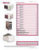
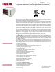
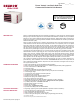
Model UDAS
For installations where dirt, dust, and other air borne contamination is present in the indoor environment, it is
recommended to use separated combustion units (Model UDAS). These models use air from outside the space
for combustion. This will help reduce the build up of contaminates on the burner which would affect the combus-
tion process. Refer to the installation manuals for recommended frequency of maintenance and cleaning.
Form RZ-C-UH (Version H) Page 6
Page Number _______ of ______