Owners Guide and Installation Instructions Gas Heavy Duty Water Heater 260 Litre Models This water heater must be installed and serviced by an authorised person. Please leave this guide with a responsible officer.
Notice to Victorian Customers from the Victorian Plumbing Industry Commission. This water heater must be installed by a licensed person as required by the Victorian Building Act 1993. Only a licensed person will give you a Complia.(y).in8 T6 0.Ciceat, shCono tat. PATENTS This water heater may be protected by one or more patents or registered designs. ® Registered trademark of Rheem Australia Pty Ltd. ™ Trademark of Rheem Australia Pty Ltd.
CONTENTS HOUSEHOLDER – We recommend you read pages 4 to 13. The other pages are intended for the installer but may be of interest. About Your Water Heater............................................................4 How Your Water Heater Works...................................................8 Regular Care ................................................................................9 Save A Service Call ...................................................................11 Installation..................
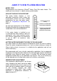
ABOUT YOUR WATER HEATER MODEL TYPE Congratulations for choosing a Rheem® Heavy Duty Gas water heater. The model you have chosen is a quick recovery water heater. HOW HOT SHOULD THE WATER BE? The water heater features a user adjustable thermostat, which allows you to personally choose the most suitable temperature for your hot water needs. Refer to “Temperature Adjustment” on page 4. To meet the requirements of the National Plumbing Standard the temperature of the stored water must not be below 60°C.
ABOUT YOUR WATER HEATER To increase the water temperature to 65°C, turn the gas control knob anticlockwise to a setting of ‘7’. Refer to “Hotter Water Increases the Risk of Scald Injury” on page 4. WARNING This water heater is not intended to be operated, adjusted or tampered with by young children or infirm persons. Young children should be supervised to ensure they do not interfere with the water heater.
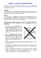
ABOUT YOUR WATER HEATER TO TURN OFF THE WATER HEATER If it is necessary to turn off the water heater: • Shut down the gas control (refer to “Close Down Procedure” on page 36). • Close the gas isolation valve at the inlet to the gas control. • Close the cold water isolation valve at the inlet to the water heater. TO TURN ON THE WATER HEATER • Open the cold water isolation valve fully at the inlet to the water heater. • Open the gas isolation valve fully at the inlet to the gas control.
ABOUT YOUR WATER HEATER ANODE PROTECTION The anode(s) installed in your water heater will slowly dissipate whilst protecting the cylinder. The life of the water heater cylinder may be extended by arranging for an authorised person to inspect the anode(s) and replace if required.
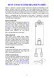
HOW YOUR WATER HEATER WORKS Water is stored in a vitreous enamel lined steel cylinder and heated by a gas burner located under the cylinder. The heat produced by the burner is transferred to the water through the base of the cylinder and through the wall of a flue pipe which passes through the centre of the cylinder. A flue baffle in this flue ensures the efficiency of the water heater is correct. The gas supply to the burner is controlled by the thermostat so the water is heated to a constant temperature.
REGULAR CARE TEMPERATURE PRESSURE RELIEF VALVE This valve is near the top of the water heater and is essential for its safe operation. It is possible for the valve to release a little water through the drain line during each heating period. This occurs as the water is heated and expands by approximately 1/50 of its volume. Continuous leakage of water from the valve and its drain line may indicate a problem with the water heater (refer to “Temperature Pressure Relief Valve Running” on page 12).
REGULAR CARE EXPANSION CONTROL VALVE In many areas, including South Australia, Western Australia and scaling water areas, an expansion control valve is fitted to the cold water line to the water heater. Water will flow from its drain line during the heating period. Operate the easing lever on the expansion control valve once every six months. It is very important you raise and lower the lever gently.
SAVE A SERVICE CALL Check the items below before making a service call. You will be charged for attending to any condition or fault that is not related to manufacture or failure of a part. NOT ENOUGH HOT WATER (OR NO HOT WATER) • Are you using more hot water than you think? Is one outlet (especially the shower) using more hot water than you think? Very often it is not realised the amount of hot water used, particularly when showering. Carefully review the family’s hot water usage.
SAVE A SERVICE CALL CAN’T LIGHT THE PILOT FLAME • Is there gas to the water heater? Check the gas isolation valve on the gas supply line is open. • Is there a normal gas supply to the rest of the premises? Try lighting another gas appliance to check. If there is no gas, call the gas supplier. TEMPERATURE PRESSURE RELIEF VALVE RUNNING Normal Operation It is normal and desirable this valve allows a small quantity of water to escape during the heating cycle.
SAVE A SERVICE CALL EXPANSION CONTROL VALVE RUNNING If an expansion control valve is fitted in the cold water line to the water heater (refer to page 23) it may discharge a small quantity of water instead of the temperature pressure relief valve on the water heater. The benefit is that energy is conserved as the discharged water is cooler. WATER HEATER APPEARS TO BE LEAKING When the water heater is first lit, or after a large usage of hot water, condensation may form on the burner of the water heater.
INSTALLATION THIS WATER HEATER IS NOT SUITABLE FOR POOL HEATING. Check the water heater is suitable for the gas type available (refer to the rating label on the water heater). WATER HEATER LOCATION An indoor model must be installed indoors and an outdoor model must be installed outdoors. The water heater should be installed close to the most frequently used outlets or with a circulated flow and return system and its position chosen with safety and service in mind.
INSTALLATION INDOOR INSTALLATION A secondary flue must be installed with an indoor water heater to discharge combustion products outside the building. The flue must be self supporting and not impose a load on the water heater. Use a slip joint or similar to allow for disconnection. There must be a vertical rise of 600 mm from the draught diverter before changing direction. The flue design and installation must comply with AS 5601. For indoor models the distances set out in the diagram should be observed.
INSTALLATION OUTDOOR INSTALLATION The water heater is to be installed at ground level on a concrete or brick plinth (fire proof base) and must stand vertically upright with the back of the water heater against an external wall or alternatively against a fireproof screen extending at least 500mm above, below and either side of the flue terminal. Failure to observe this precaution can cause problems in high wind areas. A secondary flue is not required.
INSTALLATION MAINS WATER SUPPLY Where the mains water supply pressure exceeds that shown in the table below, an approved pressure limiting valve is required and should be fitted as shown in the installation diagram (refer to diagram on page 23). Model 260 Relief valve setting 1000 kPa Expansion control valve setting * 850 kPa Max. mains supply pressure With expansion control valve 680 kPa Without expansion control valve 800 kPa * Expansion control valve not supplied with the water heater.
INSTALLATION Two Temperature Zones Using a Temperature Limiting Device CIRCULATED HOT WATER FLOW AND RETURN SYSTEM If a Rheem water heater is to be installed as part of a circulated hot water flow and return system, a storage water heater able to provide a hot water outlet temperature of at least 60°C must be used. Note: The thermostat must always be set to at least 60°C. Refer to the diagram on page 19.
INSTALLATION These conditions may result in either water at a temperature exceeding the requirements of AS/NZS 3500.4 being delivered to the hot water outlets in the ablution areas, or the device closing completely and not delivering water at all, or the device failing. Under either condition, the operation and performance of the device cannot be guaranteed.
INSTALLATION DIMENSIONS AND TECHNICAL DATA Indoor Model litres Storage capacity Mass (tank) Empty kg kg Full Gas Details 620 260 260 98 358 Outdoor 630 260 260 106 366 Hourly Gas Consumption (MJ) Min. Gas Pressure (kPa) Test Point Gas Pressure (kPa) Max. Gas Pressure (kPa) 620 260, 630 260 620 260, 630 260 620 260, 630 260 620 260, 630 260 Natural 50 1.13 1.00 Propane 47 2.75 2.70 Butane 39 2.75 2.70 Town / TLP 40/36 0.75 0.35 Model numbers: N = Natural, P = Propane, B = Butane, T = Town / TLP.
INSTALLATION TYPICAL INSTALLATION – INDOOR LOCATION 21
INSTALLATION TYPICAL INSTALLATION – OUTDOOR LOCATION 22
CONNECTIONS – PLUMBING CONNECTION SIZES • Hot water connection: RP1¼/32. • Cold water connection: RP1¼/32. • Relief valve connection: RP¾/20. • Gas inlet: RP½/15. All plumbing work must be carried out by a qualified person and in accordance with the National Plumbing Standard AS/NZS 3500.4 and local authority requirements. All gas work must be carried out by a qualified person and in accordance with the Australian Gas Installations Standard AS 5601 and local authority requirements.
CONNECTIONS – PLUMBING GAS INLET The gas connection is made to the left hand side of the gas control, through the grommet in the left hand side panel on outdoor models. The pipe work must be cleared of foreign matter before connection and purged before attempting to light the water heater. An isolation valve and disconnection union must be installed to allow servicing and removal of the water heater. Refer to the Gas Installations Standard AS 5601 for the correct pipe sizing.
CONNECTIONS – PLUMBING RELIEF VALVE DRAIN A copper drain line must be fitted to the relief valve to carry the discharge clear of the water heater. Connect the drain line to the relief valve using a disconnection union. The pipe work from the relief valve to the drain should be as short as possible and fall all the way from the water heater with no restrictions. It should have no more than three right angle bends in it. Use DN20 pipe.
MULTIPLE INSTALLATIONS A multiple installation of Rheem water heaters on a single manifold or multiple manifolds is possible, using the Rheem Equa-Flow® manifold system, where large volumes of hot water are required. The Equa-Flow principle will function with water heaters in line, around a corner or in rows back to back (refer to the diagrams on page 27). The cold water and hot water manifolds must be designed to balance the flow from each water heater.
MULTIPLE INSTALLATIONS In Line Manifold Single Bank of Water Heaters Multiple Banks of Water Heaters Angle Manifold Back to Back Manifold TPR Valve Drain Line Common Discharge Point 27
MULTIPLE INSTALLATIONS LEGEND TYPICAL INSTALLATION – RHEEM HEAVY DUTY GAS WATER HEATERS 28
MULTIPLE INSTALLATIONS In Line Manifold NOTES: 1. Minimum recommended space between wall and back of water heater is 100 mm. Angle Manifold 2. A minimum of 900 mm (E* & F*) should be left in front of the water heater for access, servicing and water heater removal.
MULTIPLE INSTALLATIONS MANIFOLD ARRANGEMENT Hot Manifold Assembly Cold Manifold Assembly 30
COMMISSIONING TO FILL AND TURN ON THE WATER HEATER The gas pilot or burner must not be lit until the water heater is filled with water. • Open all of the hot water taps in the building (don’t forget the showers) and supply cock(s) and valve(s) in the system. • Open the isolation valves fully on the cold and hot water branches to the water heater(s) installed in a bank. • Open the cold water isolation valve on the cold water line to the water heater(s). Air will be forced out of the taps.
COMMISSIONING TO TURN OFF THE WATER HEATER If it is necessary to turn off the water heater on completion of the installation, such as on a building site or where the premises is vacant, then: • Shut down the gas control (refer to “Close Down Procedure” on page 36). • Close the gas isolation valve(s) at the inlet to the gas control(s).
LIGHTING THE WATER HEATER FOR YOUR SAFETY READ BEFORE LIGHTING Warning: This gas water heater is designed to operate reliably and safely as long as the operating instructions are followed exactly. You must comply with these lighting instructions at every stage. Make sure the water heater is filled with water and the water supply is on, otherwise serious damage to the vitreous enamel cylinder lining and plastic components may occur.
LIGHTING THE WATER HEATER LIGHTING INSTRUCTIONS Using the gas control light the water heater as follows: 1. Stop, read the safety information on page 33. 2. Turn the gas control knob fully clockwise to the “z” (off) position. 3. Wait five (5) minutes so any build up of unburnt gas can escape. If you then smell gas, stop and follow “C” in the safety information. If you do not smell gas, proceed to step 4. 4. Turn the knob to the “·” (pilot) position. 5.
LIGHTING THE WATER HEATER The main burner will now automatically ignite when heating is required and extinguish when the water has been heated to the set temperature. If the main burner does not light at the selected setting, the water may already be at the selected temperature. Note: Never press the igniter button while the top knob is in a numbered position. TEST THE WATER HEATER AFTER INSTALLATION • The operation of the water heater must be thoroughly checked by the installer.
LIGHTING THE WATER HEATER CLOSE DOWN PROCEDURE 1. Turn the gas control knob to the “·” position (pilot). This setting will leave the pilot flame alight however the main burner will not be able to light. 2. Turn the gas control knob to the "z" (off) position. This setting shuts the gas control down completely.
DRAINING THE WATER HEATER To drain the water heater: • Turn off the water heater (refer to “To Turn Off The Water Heater” on page 32). • Close all hot water taps. • Operate the relief valve release lever - do not let the lever snap back or you will damage the valve seat. Operating the lever will release the pressure in the water heater. • Attach a hose to the water heater drain cock. Let the other end of the hose go to a drain. • Open the drain cock. • Operate the relief valve again.
WATER SUPPLIES Your water heater is manufactured to suit the water conditions of most Australian metropolitan supplies. However, there are some known water supplies which can have detrimental effects on the water heater and its operation and/or life expectancy. If you are unsure of your water quality, you can obtain information from your local water supply authority.
RHEEM MAINS PRESSURE WATER HEATER WARRANTY – AUSTRALIA ONLY – WARRANTY CONDITIONS 1. This warranty is applicable only to water heaters Accredited Service Agent’s premises and the installed site shall be the owner’s responsibility. 5. Where the water heater is installed in a position that does not allow safe, ready access, the cost of accessing the site safely, including the cost of additional materials handling and / or safety equipment, shall be the owner’s responsibility. 6.
RHEEM MAINS PRESSURE WATER HEATER WARRANTY – AUSTRALIA ONLY – WARRANTY Rheem will: a) Repair or, if necessary replace any Rheem water heater; or b) Replace any component (or, if necessary, arrange the installation of a new water heater), which falls within the Warranty Periods specified below, subject to the warranty conditions and exclusions.