
Installation Guide


Determining Pipe Size by Length and Capacity
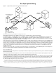
We will need to calculate the total load of the system and each branch. In our sample system, Figure 1, measure and add the lengths
of pipes at each section. Total the BTU of the appliances for each branch line and the main trunk line back to the gas meter. Select the
appropriate sized gas line based on length, BTU capacity, and pressure drop from Table 2, Table 3, or Table 4.
You can see that, in a typical gas system, a tankless water heater with a capacity of 199,900 BTU will require a 1-inch pipe size for a
20 ft branch length (based on the 0.3 in w.c. pressure drop in Table 2). The same appliance would require just a ½” pipe size based on
Table 4 the 3.0 in w.c. pressure drop.
A branch line is a pipe off the main line that feeds a group of appliances. In our example, we have two branch lines. The pipe size of
the main pipe on the branch must be sized based on the total BTU of all the appliances on that branch line and pipe length.
The trunk line pipe is the main pipe from the meter/regulator that feeds the different branches. The trunk line must be sized based on
the total BTU from each branch-line system or the sum of the total BTU of all the appliances on the system and pipe length.
Items such as elbows, tees, and valves are not included in these sample calculations. Their equivalent pipe length should be included
when sizing gas systems. It is recommend that a licensed gas tradesman size, design, and install the gas system.
Pipe Sizing Formula and Factors
You can calculate the required inside diameter of the piping required for a specific appliance/system capacity and length. This
formula is from the National Fuel Gas Code (NFPA 54, ANSI Z223.1, Section 6.4.1).
Calculate Q by dividing the BTU capacity of the appliance(s) by 1,024.
Q
0.381
0.206
19.17
( )
ΔH
Cr x L
D
=
D = inside diameter of pipe (in.)
Q = input rate of appliance (s) (cubic feet)
(divide the BTU by 1,000 to get the cubic feet)
Δ H = pressure drop [in. w.c.]
L = equivalent length of pipe
Cr = gas formula factor 0.6094 for Natural Gas
To determine the allowable pressure drop, find the system static input gas
pressure using a Manometer. Then, find the highest minimum gas pressure
from all the appliances, usually listed on the appliances rating label. Subtract
the highest minimum gas pressure from the static input gas pressure to get
the difference. For example, the input static pressure is 7 in. w.c.; the highest
minimum pressure is 6 in. w.c.; leaving a difference of 1 in. w.c. In this exam-
ple the system can have a .5 in. w.c. pressure drop based on Table 3. If the
input pressure was 9 in. w.c., in this example, then a 3.0 in. w.c. pressure drop
based on Table 4 would be allowable.
For additional sizing information for Hybrid Pressure Systems, Propane Gas
Systems, and Corrugated Stainless Steel Tubing, see the 2012 Edition of the
National Fuel Gas Code, NFPA 54, ANSI Z223.1, or consult with your local gas
utility or code officials.
Rheem.com
Gas Pipe System Sizing
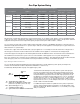
Table 1 - Gas System Branch Sizing Example based on Figure 1
Line Segment Appliance BTU Required Line Length
Minimum Pipe Size Required
0.3 w.c. drop 3.0 w.c. drop
Branch 1
E Tankless Water Heater 199,900 20 ft 1” ½”
G Gas Furnace 75,000 15 ft ½” ½”
D Branch Main Line 274.900 30 ft 1” ¾”
Branch 2
J Gas Dryer 25,000 20 ft ½” ½”
H Gas Range 55,000 30 ft ½” ½”
K Gas Logs 40,000 10 ft ½” ½”
B + C Branch Main Line 120,000 45 ft ¾” ½”
Main Trunk A Main Trunk Line 394,900 20 ft 1 ¼” ¾”