
Installation Guide

29
1
/4"
(743 mm)
27
5
/8"
(702 mm)
3
3
/8"
(86 mm)
5
1
/2"
(140 mm)
6
1
/4"
(159 mm)
17
7
/8"
(454 mm)
18
5
/8"
(473 mm)
9
3
/4"
(248 mm)
2
1
/4"
(59 mm)
5
1
/2"
(140 mm)
6
1
/8"
(156 mm)
2
1
/8"
(54 mm)
3
7
/8"
(98 mm)
2
7
/8"
(73 mm)
4
1
/8"
(105 mm)
9
1
/2"
(241 mm)
1
1
/2"
(38 mm)
CONDENSING GAS TANKLESS WATER HEATER
EZ-INSTALLATION
GUIDE
TIPS FOR A PROPER INSTALLATION
This guide is designed to provide a high-level installation
overview and address key installation questions. It does
not supplement the “Installation Instructions” in the Use
and Care Manual provided with the water heater. All
instructions and installation requirements, as well as any
local or national codes, must be followed.
Included Accessories:
Remote Control - Remote Wire - Mounting Screws - Gas Shut-Off Valve -
Use and Care Manual with Installation Instructions (includes Warranty Certificate)
• GAS SUPPLY
REQUIREMENTS
• VENTING REQUIREMENTS
• WATER CONNECTIONS
• REMOTE INSTALLATION
• POWER REQUIREMENTS
Rheem.com
INSTALLATION ACCESSORIES
COSMETIC PIPE COVERS
These cosmetic pipe covers enhance
the installation of the water heater.
Providing protection from tampering
and hiding the plumbing.
• RTG20227 - Fits RTGH-Series models
CONDENSING TERMINATION KITS
The PVC vent terminations allow for an aesthetic and easy
installation of the High Efficiency Tankless Water Heaters.
HORIZONTAL VENT
TERMINATION
Low Profile Design for two pipe
Direct Vent, fits PVC or CPVC
venting. Installed Dimensions:
11-¾” x 8” x 2-½”
• SP20286 - for 3” PVC Venting
• SP20285 - for 2” PVC Venting
HORIZONTAL OR VERTICAL
CONCENTRIC TERMINATION
Combines a 2-pipe vent system to a
single concentric through the wall or roof
penetration. Designed for two pipe Direct
Vent, fits PVC or CPVC venting.
Installed Dimensions: 39” long x 7-¼” dia.
• SP20245 - for 3” PVC Venting
• SP20897 - for 2” PVC Venting
EZ-LINK™ CABLE
Easily connect two Tankless
units together. When
connected the units will
operate as a single system.
Compatible with all current
models.
• RTG20040
Must use two identical models
SERVICE VALVES
Webstone-Brand Tankless
Service Valves, Clean Brass
for California Low Lead Code.
• RTG20220AB
includes Cold and Hot Water set and
Pressure Relief Valve
FLUSH KIT
The Tankless Flush Kit connects
to the service valves for an easy
way to flush and de-scale your
tankless water heater.
• RTG20124
includes pump, hoses,
and 5 gallon bucket.
In keeping with its policy of continuous progress and product improvement, Rheem reserves the right to make changes without notice.
This guide covers Rheem, Ruud, Richmond,
and EcoSmart-branded condensing direct vent
tankless water heaters.
PRINTED IN U.S.A. 06/18 AP16559-2 Rev 03
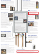
INSTALLATION CONNECTIONS
1. GAS SUPPLY
An improperly sized gas line will cause operational issues with this water heater. The gas system must be sized to
allow enough gas for the water heater to operate at full capacity. A minimum of a ½” black iron pipe is required.
See the “Gas Piping” section in the “Installation Instructions” in the Use and Care Manual or the National Fuel
Gas Code for specifics on gas piping and installing your water heater.
Flexible connectors are permitted; however, verify that the BTU rating of the connector meets or exceeds the
requirement of the water heater. Just the size of the fittings on the ends is not enough.
- ¾” NPT PIPE THREAD with Pressure Tap
2. COLD WATER
- ¾” NPT PIPE THREAD with Inlet Filter
3. HOT WATER
- ¾” NPT PIPE THREAD with Service Drain
1
2
3 5
4
4. CONDENSATE DRAIN
- ½” SLIP FIT Secure Line with Clamp
5. REMOTE CONNECTION
- Two-Terminal Connection
Copper pipe is recommended. PVC and PEX are permitted as local codes allow. Pipe sizes less that ¾” are not
recommended as you could experience pressure loss at your fixtures.
Copper pipe is recommended. PVC and PEX are permitted as local codes allow. Pipe sizes less that ¾” are not
recommended as you could experience pressure loss at your fixtures.
The factory shipping cap must be removed as this unit will produce an extreme amount of condensate and
must be connected to a drain. A flexible ½” inside diameter line is recommended. Ridged PVC can be used.
Leave an air gap at the drain and DO NOT form a trap in the line.
There is no need to remove the front cover of the unit to connect the remote as there are no connection points
inside the unit. The connection is under this cover on the bottom of the unit. Remove the single screw holding the
cover on, insert the wire through the grommet, and connect the wires to the screw terminals.
6. CONDENSATE SERVICE DRAIN
- No Need to Connect
6
This is not a physical drain connection, but used in the event of service. DO NOT connect this to a drain.
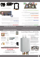
MOUNTING AND VENTING
A. EXHAUST VENT
- 2” SCH 40 PVC Pipe
The exhaust vent must terminate outside of the building. The system is designed for use with solid core schedule
40 PVC; foam or cellular core is not permitted. A list of acceptable materials is located in the “Venting” section
of the “Installation Instructions” in the Use and Care Manual. DO NOT attempt to use any other material. DO
NOT combine or connect this vent to any other vent from another appliance or run into a chimney. Unauthorized
installation of this vent system can result in the improper operation or failure of this water heater. Read and follow
all recommended installation instructions in the “Venting” section of the “Installation Instructions” in the Use and
Care Manual.
B. INTAKE VENT
- 2” PVC Pipe
The air intake vent must terminate outside of the building. It is not acceptable to allow the unit to draw air from
inside the building as it may cause operational issues with the water heater. This system is designed for use
with schedule 40 PVC pipe. A list of acceptable materials is located in the “Venting” section of the ”Installation
Instructions” in the Use and Care Manual. DO NOT connect this vent to any other vent, appliance, or run into a
chimney. Unauthorized installation of this vent system can result in the improper operation or failure of this water
heater. Read and follow all recommended installation instructions in the “Venting” section of the “Installation
Instructions” in the Use and Care Manual.
A
B
D. DIMENSIONS
This water heater requires just ½” clearance on the left and
right sides; 12” from the top; and 24” from the front. DO
NOT stack items on or in front of the unit. This chart shows
the basic dimensions of the water heater.
Piping Dimensions from Center Line and the Back.
PROBLEMS OR QUESTIONS
CALL CUSTOMER SERVICE AND SUPPORT
We are here to answer any question you might have about this
Tankless Water Heater or any Tankless Parts and Accessories.
For Technical Support Call .............................1-800-432-8373
Open 7 Days a Week • 7 am - 7 pm CST
DO NOT RETURN THIS WATER HEATER
TO THE STORE