
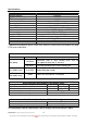
Specifications
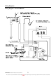
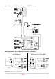
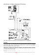

TM024 Premier Loline Solar Drain back Service Instructions REV: A
D.O.I: 12/12/2007
This document is stored and maintained electronically by Service. All printed copies not bearing this statement in RED are deemed “uncontrolled”
8
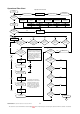
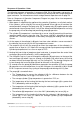
Operational Flow Chart
Plug In
Power On
Operational Flow Chart
Self
check routine
normal?
Red LED 1 flash
Rectify fault Isolate Power
YES
Software
malfunction
Hot sensor open
circuit
Hot sensor short
circuit
Red LED 2 flash
Cold sensor open
or short circuit
Red LED 3 flash
Thermistors open
or short circuit
Red LED 4 flash
Sensor strip
unplugged
Red LED 5 flash
NO
Is hot
sensor temp
> or = tank temp
+ 12ºC?
YES
Green LED
5 flash
NO
Green LED
4 flash
Notes
(1) Self check routine is
performed every 20 milliseconds
regardless of stage of operation.
(2) Tank temp = average temp of
sensor strip top 3 thermistors.
(3) Pump 2 (auxiliary pump) is
optional and is utilised only if
collector heights are between 9
& 18 metres high.
Is hot
sensor temp <
5ºC above tank
temp?
Is cold
sensor temp >
75ºC?
Is hot
sensor temp >
95ºC?
Is hot
sensor temp
< 20ºC?
Is hot
sensor temp < 4ºC
above cold sensor
temp?
YES
NO
NO
NO
NO
NO
A
Restore Power
A
Pump 1 off
YES
YES
YES
YES
Is tank
temperature > or
= 75ºC?
The pump(s) speed is pulse
controlled by the control board
to limit the temperature rise of
the fluid across the collectors
to 10ºC. For pump 1 this will
occur from this period onwards
until pump 1 is switched off by
the control board.
NO
YES
Is hot
sensor temp < 4ºC
above cold sensor
temp?
Is hot
sensor temp <
5ºC above tank
temp?
Is cold
sensor temp >
75ºC?
Is hot
sensor temp >
95ºC?
Is hot
sensor temp <
20ºC?
NO NO NO
YES
YES
YES YES
Pump relay
energised
NO
YES
Pump 1 & 2 on
Is tank
temperature > or
= 75ºC?
Green LED
on (solid)
YES
Pump 1 off
YES
NO
NO
Pump relay
de-energised (if on)
Green LED
2 flash
Green LED
3 flash
Pump 1 & 2 on low
(pulse controlled)
Pump 2 off
1
5
s
e
c
2 min
1 min
0 sec
30 sec
Pump 1 & 2 speed
pulse controlled
(1)
(2)
(2)
(2)
(2)
(2)
(3)
(3)
(3)
(3)