
Use and Care Manual

INSTALLATION MANUAL
5
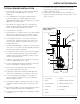
TYPICAL SEWAGE INSTALLATION
1. This installation must be in accordance with the National
Electric Code and all applicable local codes and
ordinances.
2. For sump applications, follow typical sump installation
instructions (page 3). For effluent applications, follow
typical effluent installation instructions (page 4). For sewege
applications, proceed to step 3.
3. Use a basin that is large enough to accommodate the
pump. The basin diameter should be a minimum of 18
inches and the depth a minimum of 24 inches.
4. Clean the basin of all debris.
5. Set the pump on a solid, level surface. Do not place pump
directly on clay, earth, gravel, or sand. A brick or block
may be installed under the pump to provide a solid base.
6. Position pump in the basin so the switch is away from
incoming water. Verify the float switch has at least 1 inch
clearance to the side wall of the basin and is free of any
possible obstructions.
7. Install discharge plumbing according to local, regional and
state codes. Do not reduce the discharge pipe size below
that which is provided on the pump.
8. If required, drill a 1/8 in. “weep” hole in the discharge pipe
1 in. above the pump discharge. Water stream will be
visible from this hole when the pump is running. The hole
must be cleaned periodically.
9. If optional control device or float is used, follow mounting
instruction supplied with device or float.
10. A union should be installed above the basin to allow easy
removal of the pump for cleaning and service.
11. Install a check valve (required) to prevent back-flow.
It should be installed above the union.
12. A gate valve or ball valve should be installed above the
check valve as required by local, regional or state codes.
13. Connect remaining discharge pipe. The remainder of
the discharge line should be as short as possible with a
minimum number of turns.
14. A vent pipe is required. It removes gases and odors and
should be installed as required by local, regional or state
codes.
15. Secure power supply cord to discharge pipe using cable or
zip ties to prevent possible switch entanglement.
16. Connect pump power supply cord to a properly grounded
receptacle.
17. Fill the basin with water. The pump will start when the
water level has reached the switch-on level. Verify the
pump is operating normally.
18. Install a basin cover and gasket to prevent debris from
falling into the basin, prevent personal injury and to contain
gases and odors.
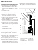
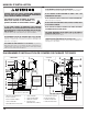
Figure 7: Submersible
Sewage Pumps
1. Check Valve 7. Switch
2. Union 8. Minimum Diameter (18 in.)
3. Discharge Pipe 9. Minimum Depth (24 in.)
4. Inlet Pipe 10. Gasket/Basin Lid
5. Basin 11. Vent Pipe
6. Pump
1
3
5
2
7
6
4
8
9
10
11