
User Guide

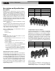
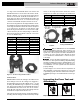
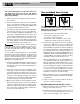
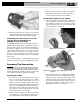
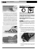
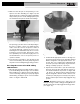
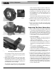

Figure 13 – Damaged Ring Pocket
Figure 14A – Placing V2 Actuator Tips Into XL-C Ring
Pockets
Figure 14B – Placing V2 Actuator Into XL-C Ring Pockets
At An Angle For Additional Clearance
Do not hang the actuator and tool from the ring. The
tool and actuator could fall from the ring and cause
serious injury or death.
4. Make sure that the ring is square to the tube and fit-
ting and depress the press tool switch. Keep fingers
and hands away from the actuator and ring to avoid
crushing injuries in the attachments and between
the attachments and surroundings.
The pressing cycle takes 4-8 seconds depending
on the press tool. Once a press cycle begins and the
8
ProPress
®
Fitting System
rollers contact the actuator, the press tool will lock on
and automatically complete the press cycle. Re -
leasing the tool switch will not stop the tool once the
pressing process has begun. This insures consis-
tent, repeatable press connection integrity. If the tool
should malfunction, refer to the specific press tool
operator’s manual.
The ProPress rings and the ProPress XL-C rings are
designed to fully close during the pressing process.
5. After the pressing operation is complete, squeeze the
actuator arms to open the actuator tips and remove
from the ring.
6. Remove the ring from the fitting. Avoid any sharp
edges that may have formed on the fitting during
the pressing operation.
Inspecting The Press Connection
1. Inspect the pressed fitting. If the fitting is supplied with
a control label by the fitting manufacturer, remove it
(Refer to Figures 6B). Control labels are supplied by
the manufacturer to indicate that the fitting has not yet
been pressed. Removal of the control label indicates
to others that the connection has been pressed.
Look for the following:
• Excessive misalignment of the tubes. Note that a
slight amount of misalignment at the pressed con-
nection is considered normal.
• Tubes that are not fully inserted into the fitting – dou-
ble check the insertion marks made on the tube to
see that they are still aligned with the end of the fit-
ting.
• Incorrect jaw or ring alignment with the fitting con-
tour, distorted or deformed fitting.
• Any other issues per the fitting manufacturer.
If any of these problems are found, then removal of
the fitting is required and a new fitting and tube will
need to be prepared and pressed in its place.
2. If inspecting ProPress fittings, check and confirm the
presence of the ProPress witness mark in one of
the hex flats (See Figure 15). This unique mark con-
firms that the proper RIDGID Jaw set, designed
specifically for the ProPress Fitting System was used
to make the pressed connection. This witness mark is
a trade mark of the Ridge Tool Company. Absence of
the witness mark may invalidate the system manu-
facturer’s warranty. The ProPress XL-C systems do
not have a witness mark.
Damaged