
User Guide

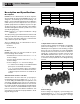
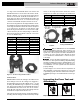
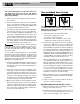
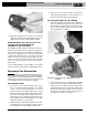
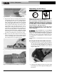
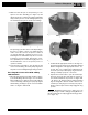
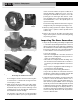

Figure 5 – Pulling The Jaw Set Mounting Pin Out
3. Slide the attachment into the press tool and fully
engage the attachment mounting pin. The press tool
will not function unless the pin is fully engaged.
Calibrating The Pressing Tool For The
Specific Pressing Attachment
(320-E Pressing Tool Only)
The RIDGID 320-E Pressing Tool includes a feature to
help insure that complete press connections are made. To
use this feature, when a press attachment is installed on
the 320-E, a calibration cycle is done. The 320-E then
compares that calibration cycle to each press connection
made. If the press connection does not match the cali-
bration cycle, the 320-E alerts the user that a pressing
error has occurred so that the operator can take appro-
priate action.
See the 320-E manual or contact Ridge Tool Technical
Service if you have any questions regarding this feature.
Preparing The Connection
These are generalized instructions. Always fol-
low the fitting manufacturers specific installation instruc-
tions. Failure to follow the fitting manufacturer’s installation
instructions may lead to an improper press connection and
cause leaking connections and property damage.
Preparing the Tube
1. If necessary, cut the desired length of the proper
tube for use with the fitting system. Use a tubing
cutter or other method that provides a clean cut
square to the axis of the tube. If using a vise or other
method to hold the tube during cutting, make sure that
the vise is far enough from the end of the tube not to
damage the section of tube that is inserted into the fit-
ting. Scratches on the outside diameter of the tube
and deformed tube can cause leaks.
2. Deburr the tube end inside and out with a file, ream-
er, deburring tool or other suitable tool. Burrs can cut
the sealing element of the fitting and cause leaks.
3. Clean the end of the tube of all dirt, oil and grease.
Improperly prepared tube can cause improper con-
nections, leaks and other property damage.
Inserting the Tube into the Fitting
1. Inspect the fitting per the manufacturer’s instructions
to be sure all parts are present, in place and free of
dirt and debris. If fitting parts are missing or dirty,
this can cause improper connections, leaks and other
property damage. See Figure 7.
Figure 6A – Inspection of the ProPress Fitting per the
Manufacturer’s Instructions
Figure 6B – Inspection of XL-C Fitting Prior to Tube
Insertion
2. In some systems, there is a requirement to mark the
tube before insertion. Check the fitting manufacturer’s
instructions, and if required, mark the tubing with a
permanent marker at the appropriate distance from
the tube end. This gives a visual reference that the
tube has been fully inserted into the fitting prior to
pressing the connection. See Figure 7.
5
ProPress
®
Fitting System
NOTICE
Seal
Grip
Ring
Control
Label