
Use and Care Manual


Ridge Tool Company
11
SeekTech
®
ST-510 Line Transmitter
manufacturers and frequencies,
see the Manufacturers
Frequency Table on page 16.
Consult your receiver/lo-
cator operator’s manual or manufacturer for more infor-
mation on those products.
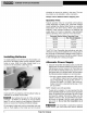
To load other manufacturers frequency information
• Press the menu key
(Figure 4).
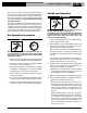
• Use the UP/DOWN keys to scroll to “Manf. Menu”
and press the select key. This will bring up the list of
manufacturers.
(Figure 17).
• Use the UP/DOWN keys to scroll to the appropriate op-
tion and press the select key.
(Figure 18).
Figure 17 – Manufacturers Menu Selection
Figure 18 – List of Manufacturers (First Screen)
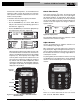
When using the frequency keys while set up for a dif-
ferent manufacturers receiver/locator, the lowest fre-
quency is controlled by the top (closest to the readout)
frequency key. The frequency moves higher with
each key further away from the readout. If there are
more than four frequencies, pushing the frequency
key furthest from the readout multiple times will in-
crement the frequency to the next higher frequency.
(See Figure 19.)
As always, the frequency selected is
displayed on the readout.
Figure 19 – Frequency Buttons – Other Manufacturer
Receiver/Locator
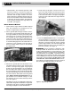
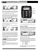
Check The Circuit
Look at the resistance (Ω - ohms), the voltage (V) and
the current (mA) displayed on the screen
(See Figure
20)
. Display numbers are approximate. Generally the
lower the ohms (total resistance) the more efficiently
current can be added. Lower total resistance indicates an
efficient circuit and requires less voltage to induce a
signal in the line.
Figure 20 –Display Panel
The transmitter will beep faster if the resistance is lower
and slower if the resistance is higher.
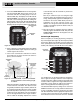
Adjust Current
Use the up and down keys to adjust the amount of cur-
rent in milliamps (mA)
(Figure 21)
.
More current gives a stronger signal. Less current pro-
longs battery life. Signal strength measured by the re-
ceiver is directly proportional to the amount of current on
the line. More current means a stronger signal will be re-
ceived by the receiver.
To prolong battery life and reduce the chance of the sig-
nal “bleeding over” onto adjacent lines, use the minimum
amount of current needed to get a clear reading on the
receiver.
Figure 21 – Current Selection (Up and Down Keys)
There are 7 current levels that the user can choose
from: 5, 25, 50, 100, 200 or 400 mA.
)
)
)
)
)
)
Low
Med Low
Med High
HIgh
Frequency
Selected
)
)
)
Resistance
Voltage
Current