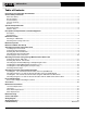
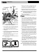
Power Drives Operator’s Manual 300 Power Drive WARNING! Read this Operator’s Manual carefully before using this tool. Failure to understand and follow the contents of this manual may result in electrical shock, fire and/or serious personal injury. TRADE TOOL WWW.TRADETOOLSUPPLY.COM • Français – 25 • Castellano – pág.
300 Power Drive Table of Contents Recording Form for Machine Serial Number..............................................................................................................1 General Safety Information Work Area Safety........................................................................................................................................................2 Electrical Safety ..............................................................................................................
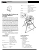
Power Drives 300 Power Drive Model 300 Complete pictured above including Stand, Threading Carriage, Tool Tray and Oiler. 300 Power Drive Record Serial Number below and retain product serial number which is located on nameplate. Serial No.
300 Power Drive General Safety Information WARNING! Read and understand all instructions. Failure to follow all instructions listed below may result in electric shock, fire, and/or serious personal injury. SAVE THESE INSTRUCTIONS! Work Area Safety • Keep your work area clean and well lit. Cluttered benches and dark areas invite accidents. • Do not operate power tools in explosive atmospheres, such as in the presence of flammable liquids, gases, or dust.
300 Power Drive ance at all times. Proper footing and balance enables better control of the tool in unexpected situations. • Use safety equipment. Always wear eye protection. Dust mask, non-skid safety shoes, hard hat, or hearing protection must be used for appropriate conditions. Tool Use and Care • Do not use tool if switch does not turn it ON or OFF. Any tool that cannot be controlled with the switch is dangerous and must be repaired.
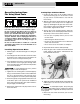
300 Power Drive Volts ............................120V Single Phase AC 25-60 Hz (230V Available On Request) Amps...........................15 Amps (36 RPM) 18 Amps (57 RPM) Controls .........................FOR/OFF/REV Switch and ON/OFF Foot Switch Figure 1 – Locked Foot Switch Weight............................77 lbs.
300 Power Drive • 418 Oiler 2. Mount power drive on the stand using bolts and wing nuts (Figure 3). • 1 Gallon Nu-Clear Thread Cutting Oil • 32 Transporter Catalog No. Model No. Description 41855 75075 41860 75435 15682 300 Only 300 Only 300 Only 300 Only 300 Complete 300 Complete 115V,25-60 Hz 115V,25-60 Hz 230V,25-60 Hz 230V,25-60 Hz 115V,25-60 Hz 1/2″ – 2″ NPT 115V,25-60 Hz 1/2″ – 2″ NPT 15722 Spindle Speed RPM Lb. Kg. 38 57 38 38 38 94 94 94 94 212 43.0 43.0 43.0 43.0 96.2 57 212 96.
300 Power Drive Quick or Self-Opening Die Head 1. Make sure Power Drive is unplugged and the directional switch is set to the OFF position (Figure 3). No. 311 Carriage w/Lever 2. Clean the speed chuck jaws with a wire brush. No. 360 Cutter Retaining Ring Assembly (2) No. 341 Reamer Set Screw (2) 3. Inspect the jaw inserts for excessive wear. Refer to the Maintenance Instructions if they need to be replaced. NOTE! For plastic and coated work pieces, special jaw inserts (Part No.
300 Power Drive Machine and Work Area Set-Up • Stand facing the directional switch. • Use the foot switch with his left foot. WARNING • Have convenient access to the directional switch, tools and chucks without reaching across the machine. To prevent serious injury, proper set-up of the machine and work area is required. The following procedures should be followed to set-up the machine: Machine is designed for one person operation. 1. Locate a work area that has the following: • Adequate lighting.
300 Power Drive Operating Instructions For Using Hand Tools Cutting Pipe with Hand Cutter 1. Position the pipe cutter on the workpiece with the cutter wheels facing up (see “Accessories” section for pipe cutters recommended for use with this Power Drive). WARNING Do not wear gloves or loose clothing when operating Power Drive. Keep sleeves and jackets buttoned. Do not reach across the machine or pipe. Do not use this Power Drive if the foot switch is broken or missing.
300 Power Drive Threading Pipe with Hand Threader Reaming Pipe with Hand Reamer WARNING To prevent serious injury, do not use selffeeding spiral reamers with the 300 Power Drive. 1. Flip the directional switch to FOR (Forward). 2. Place the reamer in the end of the pipe (see the “Accessories” section for reamers recommended for use with this Power Drive). 3. Assume the correct operating posture. 4. Rest handle on the left support bar (Figure 6) and hold the reamer handgrip with the right hand.
300 Power Drive 12. Reverse the ratchet knob. The arrow on the knob should point down. 13. Lower the threader handle below the height of the left support bar. Handle Hand Threader 14. Slide the left support bar back to its fully extended position in front of the Power Drive. 15. Lift and hold the threader handle against the left support bar. 16. Flip the directional switch to REV (Reverse). Depress and hold the foot switch down until the threader has unscrewed itself from the workpiece.
300 Power Drive Operating Instructions for Carriage-Mounted Power Drive Tools 2. Move pipe cutter down onto pipe and move carriage with carriage lever to line up cutter wheel with mark on pipe. 3. Tighten cutter feedscrew handle while keeping the cutter wheel aligned with the mark. WARNING 4. Assume the correct operating posture (Figure 11). WARNING This will allow you to maintain proper balance and to safely keep control of the machine and tools.
300 Power Drive 2. Extend reamer by pressing latch and sliding knob toward pipe until latch engages. 3. Check the directional switch to insure it is in the FOR (Forward) position. Depress and hold the foot switch down with the left foot. 4. Position reamer into pipe and complete reaming by pushing carriage lever with right hand. 5. Retract reamer bar and return reamer to the UP position. Chuck Hand Wheel Reamer Latch 3. Check that the proper size dies are in the die head.
300 Power Drive size ranges: (1/8″), (1/4″ – 3/8″), (1/2″ – 3/4″) and (1″ – 2″). The 1 /8″ pipe dies are not available for left hand die head. Bolt threading requires a separate set of dies for each bolt size. No bolt dies are available for left hand universal die heads. Die Head 1. With machine unplugged, remove die head. Lay die head on bench with numbers face up. 2. Flip throwout lever to OPEN position. 3. Loosen clamp lever approximately three turns. 4.
300 Power Drive Installing Dies in No. 815A Self-Opening Die Head (Right Hand Only) NOTE! The No. 815 Self-Opening Die Head (Figure 13) for right hand threads requires four sets of dies to thread pipe ranging from 1/8″ through 2″. One set of dies is required for each of the following pipe size ranges: (1/8″), (1/4″ – 3/8″), (1/2″ – 3 /4″) and (1″ – 2″). Bolt threading requires a separate set of dies for each bolt size. Roll Pin Size Bar Index Line Lock Screw 1. With machine unplugged, remove die head.
300 Power Drive Adjusting Nos. 141 and 161 Geared Threaders Die Die Die Flush With End of Pipe W W Cam Plate (Pipe Size) Adjustment Procedure 1. Place threader on floor or workbench with drive shaft up. Pipe Pipe Starting to Cut Thread Completed Thread A - Full Width Die Thread Thin Ring Gage D Flush (Basic Size) D One Turn Large (Maximum Size) 2. Pull knobs (Figure 15) of cam plate and rotate cam plate to desired pipe size marking on top of die head.
300 Power Drive Oversize Thread: For oversize (shallow thread) set head at bottom line on guide post. This line is marked (2T OVER). 2. Pull Knobs (Figure 15) and rotate cam plate to CD mark on top of die head. Undersize Thread: For undersize (deep thread) set head at top line on guide post. This line is marked (2T UNDER). 3. Remove worn die set (Figure 15) and insert new die set. IMPORTANT! Be sure to replace complete die set. Die numbers must correspond with slot numbers.
300 Power Drive 4. 141 Geared Threaders (Figure 19) – Pull out support bar on switch side and secure retaining ring against Power Drive body with set screws. 161 Geared Threaders (Figure 20) – Insert No. 346 Support Arms into support bars and secure retaining rings against Power Drive body with set screws. Adapter Bracket Retaining Ring Chuck Assembly Handwheel Centering Device No. 758 Loop Set Screw 5. 141 Geared Threaders (Figure 19) – Slip No.
300 Power Drive 5. 141 and 161 – Release foot switch when red STOP line appears on pinion sleeve (Figure 17). NOTE! RIDGID Geared Threaders have a jam-proof design so pinion shaft will automatically disengage if threader is accidentally run on pipe past a full thread length. 6. Turn REV/OFF/FOR switch to REV (Reverse) position. Step on foot switch and back threader off of pipe.
300 Power Drive Pipe No. 819 Nipple Chuck Chuck Handwheel No. 450/460 Tristand Vise Centering Device The RIDGID No. 819 Nipple Chuck is designed for holding short and close nipples or studs for threading. The No. 300 Power Drive should be equipped with 2 (two) support bars, No. 311A Carriage and self-opening or quick-opening die head.
300 Power Drive WARNING To prevent injury, remove wrench before turning on machine. 6. Screw nipple (Figure 24) threaded on one end into adapter by hand. Turn directional switch to ON and press down on foot switch. Ream and thread other end. Nipple Wrench Accessories WARNING Only the following RIDGID products have been designed to function with the 300 Power Drive. Other accessories designed for use with other tools may become hazardous when used on this Power Drive.
300 Power Drive Accessories for Threading by Close-Coupled Method Model No. 758 844 346 NOTE! 2. Place insert sideways on locking pin and press down as far as possible. Geared Threaders 141 161 Description Pipe Supports Loop X Drive Bar X X Support Arm (2) X If gear case does not have loop hole, use No. 3675 Adapter Bracket instead of No. 758 Loop. Model No. 840-A 460 92 Lubrication Proper lubrication is essential to trouble-free operation and long life of Power Drive.
300 Power Drive When servicing the Power Drive, only identical replacement parts should be used. Failure to follow these instructions may create a risk of electrical shock or other serious injury. If you have any questions regarding the service or repair of this machine, call or write to: TRADE TOOL IS AN AUTHORIZED RIDGID REPAIR CENTER. WWW.TRADETOOLSUPPLY.COM 503.221.