
Operator`s manual


Ridge Tool Company
5
• 418 Oiler
• 1 Gallon Nu-Clear Thread Cutting Oil
• 32 Transporter
Machine Assembly
WARNING
To prevent serious injury, proper assembly of the
Power Drive is required. Failure to mount the
Power Drive to a stable stand or bench may result
in tipping and serious injury. The following proce-
dures should be followed:
Mounting on No. 1206 Stand
1. Set up the 1206 Stand by opening legs and pushing
down on the tray. Legs should be stiff and the stand
should not wobble.
NOTE! The tristand leg stiffness can be increased or
decreased by the following procedure:
• Place stand upside down on a flat surface.
• Unlock tray so legs are loose.
• Locate the set screw on the tray leg support on the
rear leg
(Figure 3).
• Loosen the set screw to make the adjustment. To
increase stiffness, move the tray leg support up
towards the base. To decrease stiffness, move
the tray leg down towards the feet.
• Tighten the set screw (increasing leg stiffness
increases tray tension).
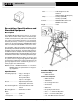
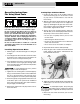
2. Mount power drive on the stand using bolts and wing
nuts
(Figure 3).
Figure 3 – 300 Power Drive Mounted on No. 1206 Stand
with 418 Oiler
Mounting 311A Carriage and Tools
1. Inspect the support bars to insure they are forward
and secured by two (2) retaining ring assemblies.
Retaining ring set screws must be tight
(Figure 4).
300 Power Drive
Spindle Weight
Catalog Model Speed
No. No. Description RPM Lb. Kg.
41855 300 Only 115V,25-60 Hz 38 94 43.0
75075 300 Only 115V,25-60 Hz 57 94 43.0
41860 300 Only 230V,25-60 Hz 38 94 43.0
75435 300 Only 230V,25-60 Hz 38 94 43.0
15682 300 115V,25-60 Hz 38 212 96.2
Complete 1/2″ – 2″ NPT
15722 300 115V,25-60 Hz 57 212 96.2
Complete 1/2″ – 2″ NPT
REV/OFF/FOR
Switch
Chuck Jaw
Handwheel
Set Screw (2)
Retaining
Ring Assy. (2)
No. 1206
Stand
Foot Switch
Wing Nut (4)
Bolt (4)
Pipe
Centering
Device
Rear Leg
Set Screw