
Operator`s manual


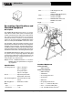

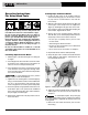

1. Make sure Power Drive is unplugged and the direc-
tional switch is set to the OFF position
(Figure 3)
.
2. Clean the speed chuck jaws with a wire brush.
3. Inspect the jaw inserts for excessive wear. Refer to the
Maintenance Instructions if they need to be replaced.
NOTE! For plastic and coated work pieces, special jaw
inserts (Part No. 97365) should be used to pre-
vent damaging the workpiece.
4. Make sure the foot switch is present and attached to
the Power Drive
(Figure 3).
Do not operate the Power Drive without a
foot switch.
5. Inspect the power cord and plug for damage. If the
plug has been modified, is missing the grounding
pin or if the cord is damaged, do not use the Power
Drive until the cord has been replaced.
6. Inspect the Power Drive for any broken, missing,
misaligned or binding parts as well as any other con-
ditions which may affect the safe and normal opera-
tion of the machine. If any of these conditions are pre-
sent, do not use the Power Drive until any problem
has been repaired.
7. Lubricate the Power Drive spindle bearings if neces-
sary according to the Maintenance Instructions.
8. Use tools and accessories that are specifically
designed for your Power Drive and meet the needs of
your application. The correct tools and accessories
allow you to do the job successfully and safely.
Accessories suitable for use with other equipment
may be hazardous when used with this Power Drive.
9. Clean any oil, grease or dirt from all handles and
controls. This reduces the risk of injury due to a tool or
control slipping from your grip.
Inspect the cutting edges of your tools and dies. If
necessary, have them replaced prior to using the
Power Drive. Dull or damaged cutting tools and
dies can lead to binding, tool breakage and poor
quality threads.
10. Clean metal shavings and other debris from the chip
tray of the 418 Oiler. Check the level and quality of the
thread cutting oil. Replace or add oil if necessary.
NOTE! Thread cutting oil lubricates and cools the threads
during the threading operation. A dirty or poor
grade cutting oil can result in poor thread quality.
Ridge Tool Company
6
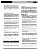
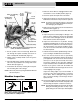
Figure 4 – No. 300 Power Drive with 311A Carriage, 360
Cutter, 341 Reamer and Die Head
2. Secure eyebolt to the 311A Carriage. Slide lever
arm through the eyebolt assembly and secure to
collar assembly with shoulder bolt
(Figure 4).
3. Tighten collar assembly thumb screw into groove
on support bar.
4. Install the 360 Cutter and 341 Reamer by inserting
arm in the slot provided in the carriage and secure
with the drive pin
(Figure 4).
5. Install 811A Die Head by inserting die head post
into the mating hole in the carriage.
NOTE! When fully inserted, spring-loaded ball will hold
die head in place.
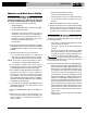
Machine Inspection
WARNING
To prevent serious injury, inspect your Power
Drive. The following inspection procedures should
be performed on a daily basis:
300 Power Drive
WARNING
No. 360
Cutter
No. 341
Reamer
No. 311
Carriage
w/Lever
Quick or Self-Opening
Die Head
Set Screw (2)
Pin
Collar
Assembly
Thumb
Screw
Shoulder Bolt
Eyebolt Assembly
Lever Arm
Support Bar (2)
Retaining Ring
Assembly (2)
Left Support
Arm
Right
Support Arm