
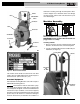
User Guide


6
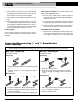
3. Insert handles into machine frame and install bolts
through belt guard bracket, machine frame and han-
dle. Install nuts to retain bolts, do not tighten.
4. Firmly tighten bolts holding loading wheel to han-
dles.
5. Adjust gap between guard and drum to less than
1
/
4
". Firmly tighten belt guard bracket bolts. Confirm
that gap between belt guard and drum is less than
1
/
4
"
to prevent fingers and other objects from being pulled
into the belt and pulley. Adjust if necessary.
Installing Cable
Do not remove the bands or cables from the cable car-
ton. The cable is under tension and can whip or strike if
released.
Manual Cable Installation – this can be used for both
Manual and AUTOFEED units.
1. Retrieve male coupling end of cable through the
center hole of the carton and pull approximately 6' of
cable from the carton.
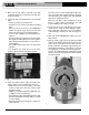
2. Connect the male coupling of the cable to the pigtail
coupling
(See Figure 4)
. Confirm connection is secure.
3. Pull short sections of cable from the carton and man-
ually feed into the drum. Do not turn machine ON.
AUTOFEED Cable Installation
1. Retrieve male coupling end of cable through center
hole of carton and pull cable from carton. Lay cable
out straight in a flat area (such as an empty paved
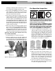
Connecting/Disconnecting
5
/
8
" and
3
/
4
" Drum Machine
Cable Couplings
Keep couplings clean and lubricated. Plunger pin must move freely and fully extend to secure connection.
New style – Plunger pin
Screwdriver required.
Connecting
1. Slide the couplings together. If needed, depress plunger
pin.
2. Confirm connection is secure. (plunger pin fully ex-
tended).
Disconnecting
1. Insert the screwdriver to depress the plunger pin.
2. Push the couplings apart until the male coupling con-
tacts the screwdriver.
3. Remove the screwdriver and push the couplings apart.
1
2
Old style – Rotating pin
Screwdriver required.
Connecting
1. Slide the couplings together.
2. Rotate pin so hash mark is away from end of cable (to-
wards “L” stamped on coupling). Confirm connection is
secure.
Disconnecting
1. Rotate pin so hash mark is towards end of cable (away
from “L” stamped on coupling).
2. Push the couplings apart.
1
3a
3b2
Hash Mark
Figure 4
K-750 Drain Cleaning Machine