
Use and Care Manual

7
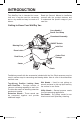
ASSEMBLY
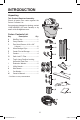
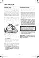
Carry Handle
Powerhead
Assembly
#10 x 3/4"
(19 mm) Pan
Head Screws (2)
Extended
Flange
#10 x 3/4"
(19 mm)
Pan Head
Screws (2)
Hose Clips
(1 on each side)
Powerhead
Assembly
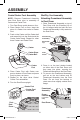
Carry Handle Assembly
1. Locate the Carry Handle and the two
(2) #10 x 3/4” (19 mm) Pan Head
Screws in loose parts bag.
2. Position the Carry Handle on top of the
Powerhead Assembly, with the Carry
Handle Extended Flange to the rear of
the Powerhead Assembly, as shown.
3. Insert a #10 x 3/4” (19 mm) Pan Head
Screw through the hole at each end of
the Carry Handle and into the Powerhead
Assembly. Tighten securely.
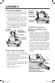
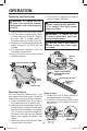
Inserting the Tug-A-Long
Positive Locking Hose with
Dual-Flex
1. Locate the end of the Tug-A-Long
Positive Locking Hose with Dual-Flex
and align it with the Drum Inlet. Align the
Hose Release Button with the Ridges on
the Vac Inlet. Push the Hose end straight
into the Vac Inlet until the Hose Release
Button fully engages the Inlet Ridges.
2. To remove Hose, rotate the end of the
Tug-A-Long Positive Locking Hose with
Dual-Flex in either direction to release
the Hose Latch from the Inlet Ridges.
Press the Hose Release Button and
pull the Hose end straight out of the
Vac Inlet.
D
R
A
I
N
Drum
Inlet
Ridges
Tug-A-Long Positive
Locking Hose with Dual-Flex
Hose Release Button
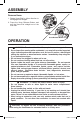
Hose Storage Clip Assembly
1. Locate the two (2) Hose Clips and
four (4) #10 x 3/4” (19 mm) Pan Head
Screws in the loose parts.
2. Place a Clip into the recess next to one
of the Latches. The Curve of the Clip
should face outward.
3. Insert a #10 x 3/4” (19 mm) Pan Head
Screw into each mounting hole and
tighten securely.
4. Repeat on the other side.
SP7033ESF.indb 7 5/30/18 3:10 PM