
Use and Care Manual


6 - English
DIRECTION OF ROTATION SELECTOR
(FORWARD/REVERSE/CENTER LOCK)
See Figure 1, page 10.
Set the direction of rotation selector in the OFF (center lock)
position to lock the switch trigger and help prevent accidental
starting when not in use.
Position the direction of rotation selector to the left of the
switch trigger for forward movement. Position the selector
to the right of the switch trigger to reverse the direction.
NOTE: The tool will not run unless the direction of rotation
selector is pushed fully to the left or right. Some attachment
heads will only operate in the forward position.
NOTICE:
To prevent gear damage, always allow the tool
to come to a complete stop before changing the
direction of rotation.
WARNING:
Battery tools are always in operating condition.
Lock the switch when not in use or carrying at your
side, when installing or removing the battery pack,
and when installing or removing attachment heads.
Avoid running the tool at low speeds for extended periods
of time. Running at low speeds under constant usage may
cause the tool to become overheated.
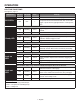
RECOMMENDED BATTERY PACKS
OCTANE
™
tools are compatible with all RIDGID
®
18 Volt
battery packs, but tool performance is maximized with
HYPER OCTANE
™
battery packs.
If you experience frequent shutoffs due to overload
protection, try using a HYPER OCTANE
™
battery pack.
OPERATION
INSTALLING/REMOVING BATTERY PACK
See Figure 2, page 10.
To install, lock the switch trigger and insert the battery
pack.
Make sure the latches on each side of the battery pack
snap in place and that battery pack is secured in the
product before beginning operation.
To remove, depress the latches.
INSTALLING/REMOVING ATTACHMENT
HEADS
See Figure 3, page 11.
The power base is designed to work with a variety of attach-
ment heads for use in different job applications.
To install an attachment head:
Lock the switch trigger and remove the battery pack.
Align one of the arrows on the desired attachment head
with the arrow on the power base. Push together, then
twist the power base until the latches click into position
and the arrow on the attachment head is aligned with the
lock icon on the power base. Pull on the head to make
sure it is securely installed before operation.
NOTE: The head can be installed at 90° angles to best
suit your application needs.
To remove an attachment head:
Pull the release tab toward the power base with one hand
and rotate the power base with the other hand. When
the arrow on the attachment head aligns with the arrow
on the power base, pull the head away from the base to
separate.