
Instructions / Assembly


Operating Instructions and Parts Manual
5
INSTALLATION (CONT'D)
5. Slope the horizontal pipe upward toward the pump to eliminate
trapping air. Sloping the pipe will also aid in priming the pump.
DRIVEN WELL (FIGURE 12 ON PAGE 11)
1. Drive the point several feet below the water table.
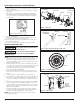
NOTE: A packer type foot valve can be installed in the well (Figure
2, Illustration B). This type of foot valve allows the well to be filled
with water when priming and makes the inlet pipe much easier to
test for leaks. Follow the manufacturer’s instructions when installing
the packer type foot valve.
As an alternative, an in-line check valve can be used with a driven
well (Figure 2, Illustration C). The pipe between the check valve and
the water level will always be under a vacuum.
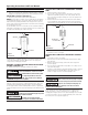
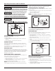
FOOT VALVE
WELL CASING
TO PUMP
WELL SEAL
Figure 2
Illustration A
Leaking joints or couplings will allow air to leak into the pipe and
cause abnormal pump operation. Make sure to use pipe joint
compound on all male pipe threads.
DUG WELL, CISTERN, LAKE AND SPRING INSTALLATION
(FIGURE 12 ON PAGE 11)
1. Install a foot valve on inlet pipe and lower into water.
The foot valve MUST be at least 18” from the
bottom of the well or sand or sediment WILL be drawn into the system.
MISE EN GARDE
Le clapet de pied DOIT au moins être
à 45,7 cm (18po) du fond du puits, sinon du sable ou des sédiments
POURRAIENT être aspirés dans le système
NOTE: When a lake is used as a water supply, make sure the
inlet pipe is deep enough to be submerged at all times. Slope the
horizontal piping upward toward the pump to prevent trapping
air. The pipe must be removed during winter months or protected
against freezing.Protect the pipe from damage from swimmers and
boats.
Install a screen around the inlet pipe to prevent
the entrapment of swimmers, wildlife and debris.
MISE EN GARDE
Installer un écran autour du tuyau
d'entrée pour éviter de piéger des nageurs, des animaux et des débris.
SHALLOW WELL PUMP WITH CONVENTIONAL STORAGE
TANK
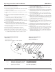
1. Install air volume control on tank.
2. Connect the copper tube from the air volume control to the
uppermost 1/8” NPT opening on the side of pump. Be sure
the connections are tight. Leaking can cause the pump not to
prime (Figure 3).
3. Install a valve and an isolator hose between the tank and the
house plumbing to aid in pump removal for servicing and for
reducing the noise transmitted to the house through the piping.
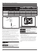
DRIVE POINT
TO PUMP
PACKER TYPE
FOOT VALVE
Figure 2
Illustration B
4. Provide a faucet at the lowest point in the system to drain the
system for service or storage.
SHALLOW WELL PUMP WITH PRECHARGED STORAGE
TANK
1. Shut off the power to the pump.
2. Open the faucet nearest the tank and allow all water to drain
from the tank.
3. Measure the tank precharge at the valve stem using a tire
pressure gauge.
4. If necessary, precharge with an air pump to 28 - 30 psi on 1/2,
3/4 and 1 HP pumps.
5. Slope the horizontal pipes upward toward the pump to prevent
trapping air. If the horizontal distance exceeds 25 feet, see
Chart 2 on page 4 for the recommended pipe size.
ELECTRICAL
Risk of electrical shock. This pump is designed
for indoor installation unless housed and protected from the elements.
Risque de choc électrique! Cette pompe est
conçue pour une utilisation à l'intérieur, sauf si elle est à l'abri et
protégée contre les intempéries.
• The voltage of power supply must match the voltage of the
pump. The motors can be converted to 115 or 230 volts by
changing the voltage selector to the desired voltage. Use a needle
nose pliers to pull the selector out approximately 1/4”, rotate and
then reinsert in correct position (Figure 7).